
Electromagnetic relay, method for connecting electromagnetic relay with PCBA (printed circuit board assembly) and time relay

An electromagnetic relay and electrical connection technology, applied in electromagnetic relays, electromagnetic relay details, relays, etc., can solve the problems of difficult assembly of welding lines, rewinding, and many flexible wires, so as to reduce the introduction of flexible wires and reduce Assembly difficulty and the effect of reducing production costs

Pending Publication Date: 2022-05-24
XIAMEN HONGFA ELECTROACOUSTIC CO LTD
View PDF0 Cites 0 Cited by
  • Summary
  • Abstract
  • Description
  • Claims
  • Application Information

AI Technical Summary

Problems solved by technology

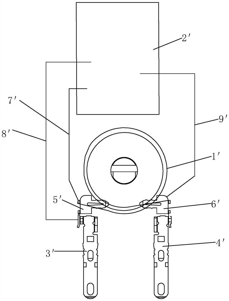
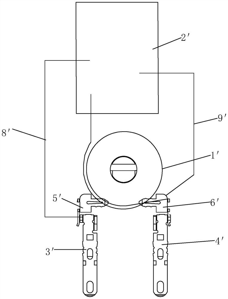
The second approach is as image 3 As shown, the end of the coil 1' is disconnected from the corresponding metal part 5', and the coil 1' is loosened at least one turn and then connected to the PCBA board 2' as an output terminal of the PCBA board 2'. However, Doing so will cause the coil 1' on the bobbin to be easily loosened and messed up, often requiring rewinding
Therefore, when using conventional relays to assemble time relays, there are problems such as introducing too many soft wires and rewinding, which leads to difficulty in product assembly and welding wires, and low efficiency

Method used


Image

  • Electromagnetic relay, method for connecting electromagnetic relay with PCBA (printed circuit board assembly) and time relay
  • Electromagnetic relay, method for connecting electromagnetic relay with PCBA (printed circuit board assembly) and time relay
  • Electromagnetic relay, method for connecting electromagnetic relay with PCBA (printed circuit board assembly) and time relay

Examples


Embodiment Construction

[0041] In the present invention, the terms "first", "second", "third" and "fourth" are only used to distinguish similar objects, rather than to describe a specific order or sequence, nor should they be construed as indicating Or imply relative importance.

[0042] See Figure 4-Figure 12 As shown, an electromagnetic relay of the present invention includes a base 1, a magnetic circuit part 2, the base 1 is provided with a first input pin 11 and a second input pin 12, and the magnetic circuit part 2 includes a coil frame 21 and an enameled wire 22; The coil frame 21 is provided with a conductive part, a first metal part 3 and a second metal part 4, the conductive part is electrically connected with the first input pin 11, and the first metal part 3 is electrically connected with the second input pin 12; The starting end of the enameled wire 22 is electrically connected to the conductive member, the enameled wire 22 is wound on the coil frame 21, and the enameled wire 22 is elec...


PUM


Abstract

The invention discloses an electromagnetic relay, a connecting method of the electromagnetic relay and a PCBA board and a time relay, the electromagnetic relay comprises a base and a magnetic circuit part, the base is provided with a first input pin and a second input pin, the magnetic circuit part comprises a coil rack and an enameled wire, the coil rack is provided with a conductive component, a first metal piece and a second metal piece, and the first input pin and the second input pin are connected through the enameled wire. The conductive part is electrically connected with the first input pin, and the first metal piece is electrically connected with the second input pin; the starting end of the enameled wire is electrically connected to the conductive component, the enameled wire is wound on the coil frame and is electrically connected to the second metal piece and the first metal piece in sequence, the part, between the first metal piece and the second metal piece, of the enameled wire has a preset length, and the part, electrically connected with the first metal piece, of the enameled wire is the tail end of the enameled wire. When the electromagnetic relay provided by the invention is used for assembling a relay with a logic function, the electromagnetic relay does not need to be rewound and replaced, so that the assembling difficulty is greatly reduced, the assembling efficiency is improved, and the production cost is reduced.

Description

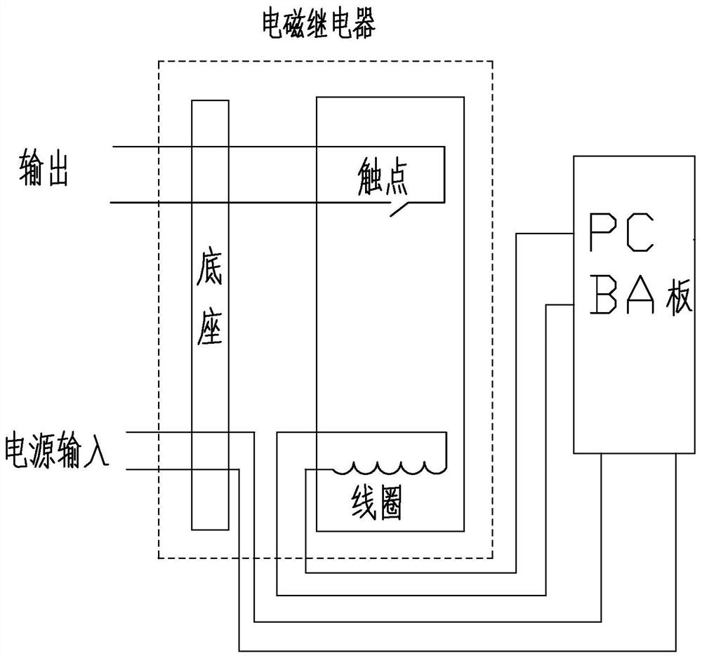
technical field [0001] The invention relates to the technical field of relays, in particular to an electromagnetic relay, a method for connecting it with a PCBA board, and a time relay. Background technique [0002] The time relay is a delay control controller using the principle of electronic electromagnetics. The traditional electronic electromagnetic time relay is generally composed of electromagnetic relay, PCBA board, etc. Its working principle is to control the opening and closing of the contacts of the electromagnetic relay by controlling the power supply to the coil of the electromagnetic relay in different time periods to achieve the corresponding functions. Its principle block diagram is as follows figure 1 As shown in the figure, the power supply is input to the PCBA board from the corresponding pins set on the base, and the PCBA board is calculated and processed to output an electrical signal to the coil of the electromagnetic relay at a certain time point, ther...

Claims


Application Information

Patent Timeline
Patent Type & Authority Applications(China)
IPC IPC(8): H01H50/14H01H50/02H01H50/44H01H50/86
CPCH01H50/14H01H50/02H01H50/44H01H50/86
Inventor 张汉顺刘金枪
Owner XIAMEN HONGFA ELECTROACOUSTIC CO LTD
Learn More