
Self-locking cross screwdriver head

A screwdriver, self-locking technology, applied in the field of medical devices, can solve the problems of the anchorage nail being implanted in the wrong position, inconvenient to remove the nail, easy to fall off, etc. Effect

Pending Publication Date: 2021-08-13
NINGBO CIBEI MEDICAL TREATMENT APPLIANCE
View PDF0 Cites 2 Cited by
  • Summary
  • Abstract
  • Description
  • Claims
  • Application Information

AI Technical Summary

Problems solved by technology

Usually, in order to allow the screwdriver tool to smoothly insert the anchorage nail cap, the connection hole will be slightly larger than the anchorage nail cap. Therefore, using such existing tools to implant the anchorage screw may easily lead to deviation of anchorage nail implantation. Or the implantation position is inaccurate, and the nails are easy to fall off during the process of taking out or implanting the nails, making it inconvenient to take out the nails

Method used


Image

  • Self-locking cross screwdriver head
  • Self-locking cross screwdriver head
  • Self-locking cross screwdriver head

Examples

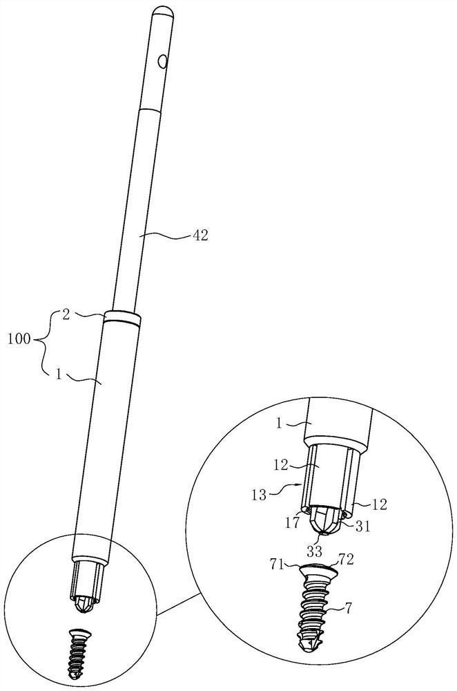
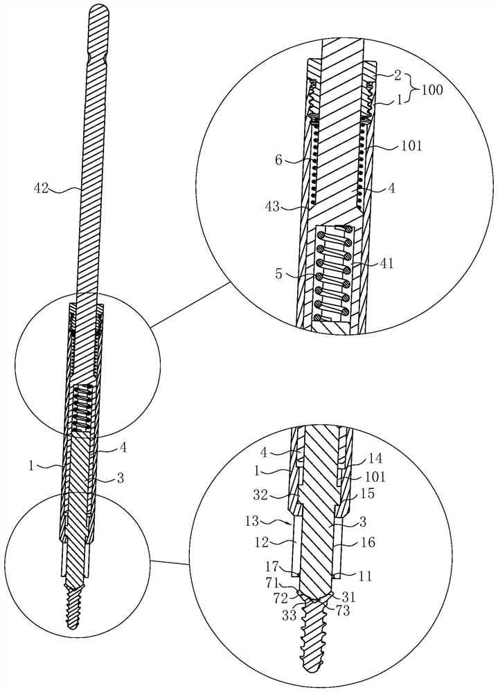
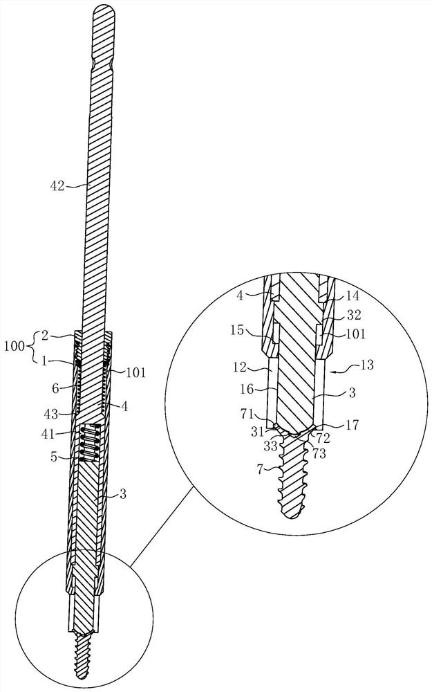

Embodiment Construction

[0023] The present invention will be further described in detail below in conjunction with the accompanying drawings and embodiments.

[0024] like Figure 1~4 Shown is the preferred embodiment of the present invention.

[0025] The self-locking cross screwdriver bit in this embodiment includes main components such as a sleeve 100 , a screwdriver bit body 3 , a screwdriver rod 4 , a first spring 5 , and a second spring 6 .

[0026] like Figure 2-4 As shown, the sleeve 100 includes a cylinder body 1 and a nut 2, and the upper end of the cylinder body 1 is screwed to the nut 2, thereby facilitating production and assembly. A through hole 101 is provided inside the sleeve 100 ; specifically, the through hole 101 is jointly formed by the cylinder body 1 and the nut 2 .

[0027] Both the screwdriver body 3 and the screwdriver rod 4 are constrained in the through hole 101 in an axially reciprocating and slidable manner. The lower end of the screwdriver bar 4 is provided with a ...


PUM


Abstract

The invention relates to a self-locking cross screwdriver head. The self-locking cross screwdriver head comprises a sleeve, a screwdriver rod, a screwdriver head body and a first spring, wherein a through hole is formed in the sleeve; an elastic clamping part for clamping the head of a supporting nail is arranged at the lower end of the sleeve; the screwdriver rod can be axially restrained in the through hole in a reciprocating sliding manner; an insertion hole with a polygonal cross section is formed in the lower end of the screwdriver rod; the upper end of the screwdriver rod penetrates through the through hole to form a holding part exposed out of the sleeve; the screwdriver head body can be axially restrained in the through hole in a reciprocating sliding manner; the upper end of the screwdriver head body is inserted in the insertion hole, so that the screwdriver rod rotates to drive the screwdriver head body to rotate; a cross rib for inserting and matching with a cross groove in the head of the supporting nail is arranged at the lower end of the screwdriver head body; when the supporting nail reversely pushes the screwdriver head body to upwards move into the through hole, the elastic clamping part clamps the head of the supporting nail; and the first spring is restrained in the insertion hole, and enables the screwdriver head body to always have a downward moving tendency corresponding to the sleeve, so that the screwdriver head is not easy to deviate from the supporting nail in the operation process.

Description

technical field [0001] The invention belongs to the technical field of medical instruments, in particular to a self-locking cross screwdriver head. Background technique [0002] With the development of society, people's requirements for quality of life are gradually increasing, and more and more people are seeking orthodontic treatment to improve their smile, correct the condition of teeth bite or correct the damage caused by injury, disease or long-term neglect of oral care. other issues. Today's orthodontic treatment requires the shortest course of treatment and the minimum cooperation of patients to obtain the best treatment effect. The microscrew implant anchorage just meets these requirements and achieves the ideal anchorage control effect. Micro-screw-type implant anchorage is a technology that has just emerged in recent years. It is implanted into the bone with micro-implant anchorage nails, and the bone is used as anchorage, which can meet the needs of anchorage du...

Claims


Application Information

Patent Timeline
IPC IPC(8): A61C8/00A61C7/00
CPCA61C7/00A61C8/0089
Inventor 孙斌黄佳敏黄杰
Owner NINGBO CIBEI MEDICAL TREATMENT APPLIANCE
Learn More