Dust collector applied to power plant

A technology for dust collectors and power plants, applied in chemical instruments and methods, separation of dispersed particles, filtration of dispersed particles, etc., can solve the problems of gas storage tank waste, reduce work efficiency, affect the operation of dust collectors, etc., to maintain normal operation, The effect of saving energy consumption

Pending Publication Date: 2021-08-13
フアネングチンメイルイジンパワージェネレーションカンパニーリミテッド
View PDF9 Cites 2 Cited by
  • Summary
  • Abstract
  • Description
  • Claims
  • Application Information

AI Technical Summary

Problems solved by technology

The commonly used dust collectors are easy to adsorb on the inner wall of the dust collector because the tiny particles or dust in the exhaust gas have static electricity. Such long-term accumulation will affect the operation of the dust collector, and the filter bag needs to be periodically cleaned during operation. Recoil expansion dust removal, often occurs when the filter bag is not completely filtered, resulting in waste of gas in the gas storage tank, requiring frequent replacement of the gas storage tank, reducing work efficiency

Method used


Image

  • Dust collector applied to power plant
  • Dust collector applied to power plant
  • Dust collector applied to power plant

Examples


Embodiment 1

[0028] refer to Figure 1~6 , which is the first embodiment of the present invention. This embodiment provides a dust collector applied to a power plant. By technically improving the existing dust collector, the whole device does not need to be attended by manpower during operation, and the dust removal and cleaning are performed automatically. , reducing labor costs and saving energy.

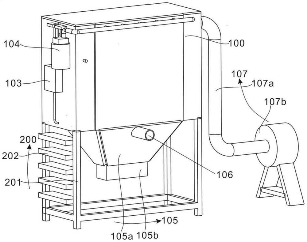
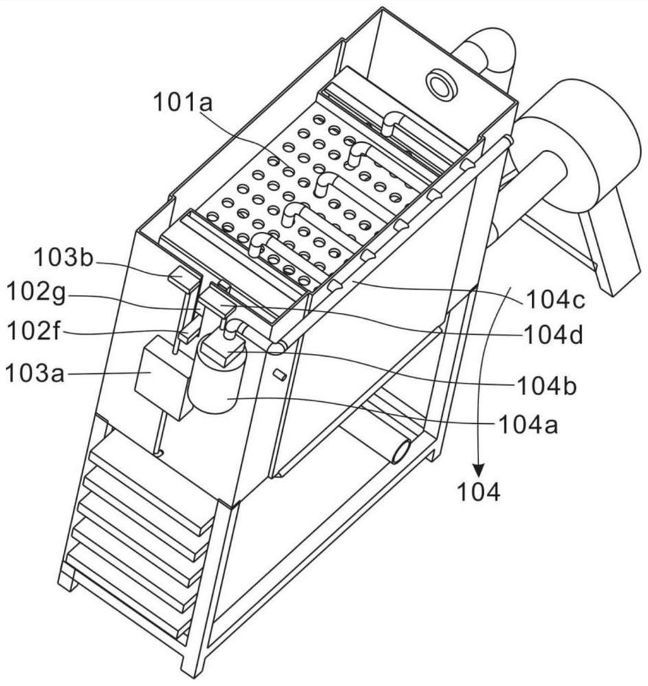
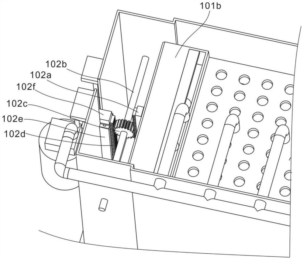
[0029] Specifically, the closed casing 100 includes a vibration lift filter assembly 101 placed in the closed casing 100, a trigger assembly 102 connected to the side of the vibration lift filter assembly 101, a power supply assembly connected to the trigger assembly 102 103 and the recoil air flow assembly 104, the hopper assembly 105 connected to the vibrating lifting filter assembly 101, and the air inlet pipe 106 arranged on the side of the hopper assembly 105;

[0030] The maintenance support assembly 200 includes a support and protection frame 201 connected to the main body 100 of the d...

Embodiment 2

[0041] refer to figure 1 , is the second embodiment of the present invention, which is different from the first embodiment in that: it also includes a heating plate 105a and a switching valve 105b. In the last embodiment, the dust remover applied to the power plant includes the technical improvement of the existing dust remover, so that the whole device does not need to be attended by manpower during operation, and the dust removal and cleaning are performed automatically, which reduces labor costs and saves energy.

[0042] Specifically, the closed casing 100 includes a vibration lift filter assembly 101 placed in the closed casing 100, a trigger assembly 102 connected to the side of the vibration lift filter assembly 101, a power supply assembly connected to the trigger assembly 102 103 and the recoil air flow assembly 104, the hopper assembly 105 connected to the vibrating lifting filter assembly 101, and the air inlet pipe 106 arranged on the side of the hopper assembly 10...


PUM


Abstract

The invention discloses a dust collector applied to a power plant. The dust collector comprises a closed shell which comprises a vibration lifting filter assembly arranged in the closed shell, a trigger assembly connected with the side surface of the vibration lifting filter assembly, a power supply assembly and a back-flushing airflow assembly which are connected with the trigger assembly, a hopper assembly connected with the vibration lifting filter assembly, and an air inlet pipe arranged on the side face of the hopper assembly; and a maintenance supporting assembly which comprises a supporting protection frame connected with a device body and a plurality of sets of pedals arranged on the side face of the supporting protection frame. The dust collector has the beneficial effects that an existing dust collector is improved, trigger type dust cleaning is carried out by utilizing weight reduction after dust accumulation of a filter bag, it is guaranteed that cleaning is effective each time, energy consumption is reduced, vibration is generated during dust removal of the filter bag, dust attached to the inner wall is shaken off, and normal operation of the dust collector is maintained.

Description

technical field [0001] The invention relates to the technical field of dust collectors, in particular to a dust collector used in power plants. Background technique [0002] In modern industrial manufacturing, a large number of polluted particles, dust and other harmful substances appear. Therefore, in order to meet the requirements of the country and protect the environment and people, the factory uses a dust removal device to process and filter the generated waste gas. The commonly used dust collectors are easy to adsorb on the inner wall of the dust collector because the tiny particles or dust in the exhaust gas have static electricity. Such long-term accumulation will affect the operation of the dust collector, and the filter bag needs to be periodically cleaned during operation. Recoil expansion dust removal often occurs before the filter bag is completely filtered, resulting in waste of gas in the gas storage tank, requiring frequent replacement of the gas storage tank...

Claims


Application Information

Patent Timeline
IPC IPC(8): B01D46/00B01D46/02B01D46/04B01D46/10B01D46/42B01D46/48
CPCB01D46/023B01D46/10B01D46/04B01D46/4263B01D46/48B01D46/72B01D46/79B01D46/71
Inventor 吴利平郭通杨敏周建松申杰丁炜
Owner フアネングチンメイルイジンパワージェネレーションカンパニーリミテッド
Why Eureka
Try Eureka