Glue pouring machine for electronic components based on improvement of glue pouring quality

A technology for electronic components and glue filling machines, which is applied to devices and coatings that apply liquid to the surface, can solve the problems of low glue filling efficiency, difficult to clean, and affect glue filling, etc., so as to increase the mixing efficiency and increase the Mixing effect, the effect of improving the efficiency of gluing

Inactive Publication Date: 2021-08-13
康生瑞
View PDF0 Cites 0 Cited by
  • Summary
  • Abstract
  • Description
  • Claims
  • Application Information

AI Technical Summary

Problems solved by technology

[0004] The purpose of the present invention is to provide a glue filling machine for electronic components based on improving the quality of glue filling, through the mixing glue valve, positioning mechanism, glue outlet mechanism, glue mixing mechanism, sealing ball, arc spring, limit channel and The design of the spiral channel solves the problem of the low glue filling efficiency and poor glue filling effect of the existing glue filling machine. When the nozzle is used, the glue at the mouth of the nozzle is easy to drop or form a glue filament, which affects the glue filling, and also causes AB glue to be polluted everywhere, which is not easy to clean. Most of the existing glue filling equipment is an integrated structure, which is not It is convenient to clean the internal glue, and the glue filling efficiency is low

Method used


Image

  • Glue pouring machine for electronic components based on improvement of glue pouring quality
  • Glue pouring machine for electronic components based on improvement of glue pouring quality
  • Glue pouring machine for electronic components based on improvement of glue pouring quality

Examples


Embodiment Construction

[0054] The following will clearly and completely describe the technical solutions in the embodiments of the present invention with reference to the accompanying drawings in the embodiments of the present invention. Obviously, the described embodiments are only some of the embodiments of the present invention, not all of them. Based on the embodiments of the present invention, all other embodiments obtained by persons of ordinary skill in the art without creative efforts fall within the protection scope of the present invention.

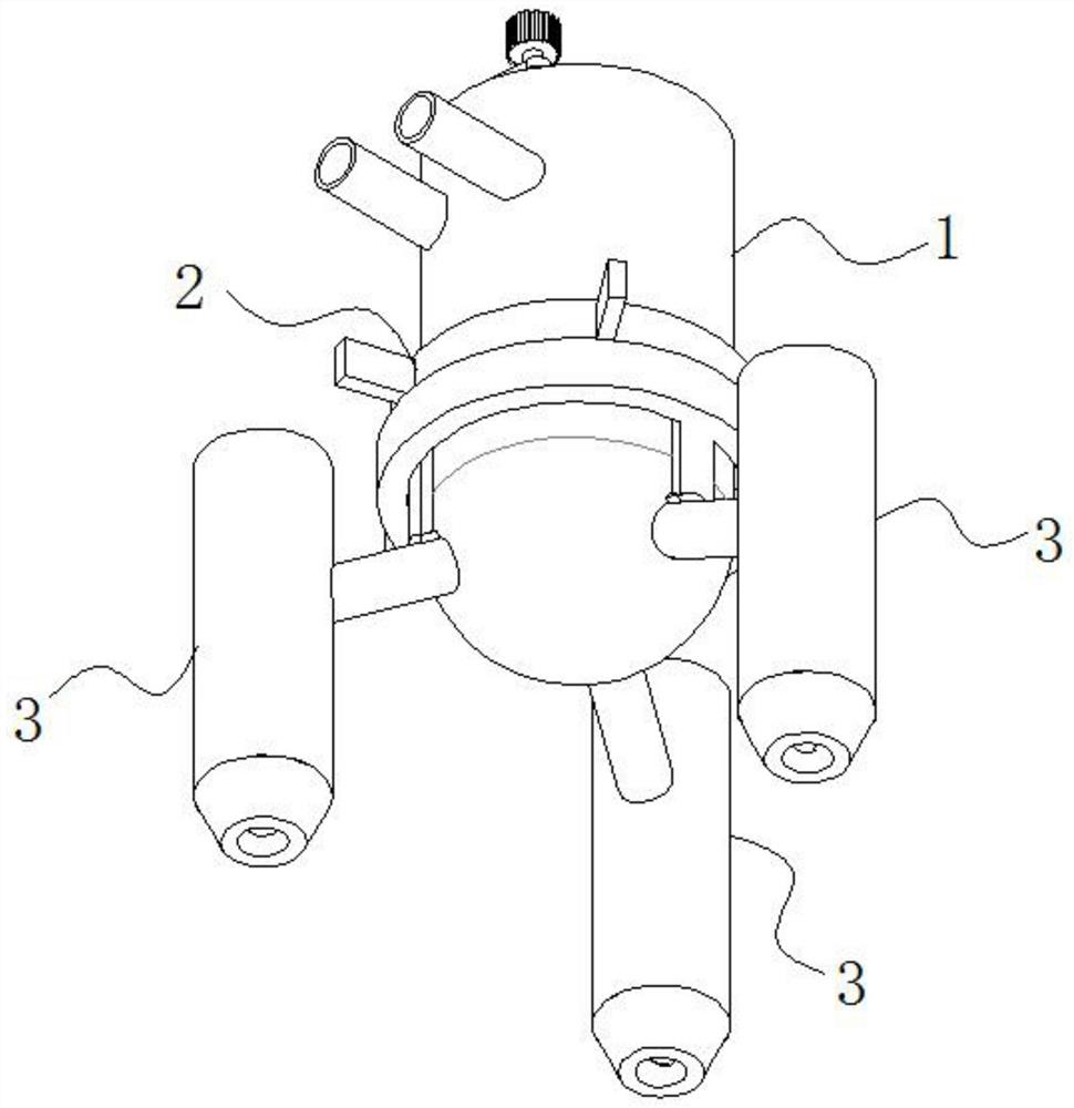
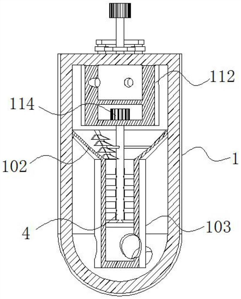
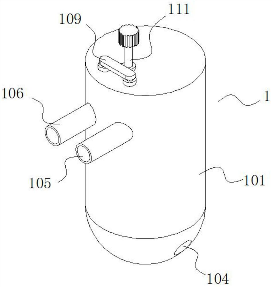
[0055] see Figure 1-12 , the present invention is a glue filling machine for electronic components based on improving the quality of glue filling, comprising a mixing glue valve 1, a positioning mechanism 2 and a glue discharging mechanism 3;

[0056] The glue outlet mechanism 3 is set along the side of the mixing valve 1, and the glue outlet mechanism 3 cooperates with the mixing glue valve 1. By setting up multiple glue outlet mechanisms 3, it can ...


PUM


Abstract

The invention discloses a glue pouring machine for electronic components based on improvement of glue pouring quality, and relates to the related technical field of electronic components. The glue pouring machine comprises a glue mixing valve, a positioning mechanism and a glue discharging mechanism. The positioning mechanism is in threaded fit with the glue mixing valve. The positioning mechanism is clamped with the glue discharging mechanism. A glue guide hopper is fixed on the inner wall of the valve body. A hollow mixing column is fixed at the bottom of the glue guide hopper. A glue mixing mechanism is arranged in the hollow mixing column. The outer wall of the hollow mixing column and the outer wall of the valve body are provided with co-location holes. The co-location holes are in clearance fit with the glue discharging mechanism. By arranging a first rotating shaft, a first scraping plate, a glue mixing strip, a second scraping plate, a third scraping plate and a glue guide plate, adhesion of mixed glue on the hollow mixing column and a sieve plate is effectively reduced through the first scraping plate and the second scraping plate, AB glue falling into the glue guide hopper is completely scraped into the hollow mixing column through the cooperation effect of the third scraping plate and the glue guide plate, and the mixing effect and the glue mixing efficiency of the glue mixing mechanism are greatly improved.

Description

technical field [0001] The invention belongs to the technical field related to electronic components, in particular to a glue filling machine for electronic components based on improving the quality of glue filling. Background technique [0002] Electronic components are now used in various places. It can be said that they are an indispensable item for people. Due to the electrical conductivity of electronic components, various electronic components need to be sealed and packaged. The most common one is The way is to use the glue filling machine to seal the electronic components. The glue filling machine mixes the A glue and the B glue and then drips them out onto the electronic components through the rubber outlet pipe. [0003] However, in the prior art, the rubber outlet pipe used is to set the pipeline into a two-way spiral type, which is automatically mixed when the AB glue enters the tank and spirally descends. Although the mixing requirements can be met as a whole, th...

Claims


Application Information

Patent Timeline
Patent Type & Authority Applications(China)
IPC IPC(8): B05C5/02B05C11/10
CPCB05C5/02B05C11/10B05C11/1036
Inventor 康生瑞
Owner 康生瑞
Why Eureka
Try Eureka