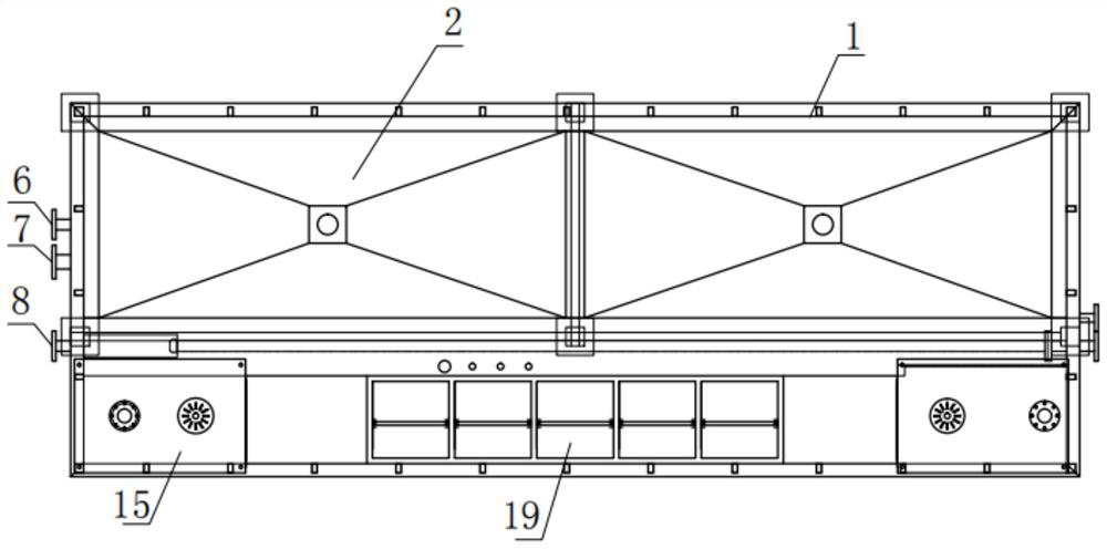
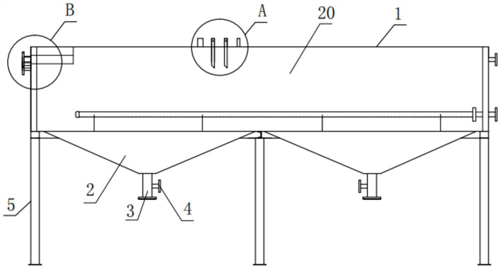
Film coating groove body

A technology for coating film and tank body, applied in the direction of coating, device for coating liquid on the surface, etc., can solve the problems of increasing the cost of coating film, affecting the quality of coating film, and troublesome cleaning of dregs, etc., to reduce the frequency of chemical replacement, Ensure the reliability of use and the effect of convenient cleaning of dregs

Pending Publication Date: 2021-08-13
ZHEJIANG HUALI INTELLIGENT EQUIP CO LTD
View PDF0 Cites 2 Cited by
  • Summary
  • Abstract
  • Description
  • Claims
  • Application Information

AI Technical Summary

Problems solved by technology

The current coating equipment mainly includes a coating tank and a transmission device. The transmission device transmits the object to be coated to the coating tank for coating. However, the existing coating tank has a flat bottom structure, and the dross of the contaminated coating solution cannot To obtain better deposition, in the coating operation, it is always stirred and mixed, which affects the quality of the coating film, and the pollution of the coating solution is very fast, requiring frequent replacement of the coating solution, which increases the cost of the coating film
At the same time, because the dross of the coating solution cannot be deposited well, the cleaning of the dross is also very troublesome, and it is not clean
The most important thing is that the existing coating tank is a single structure. When the coating tank is damaged or needs to be cleaned, the coating process needs to be stopped, which reduces the reliability and coating efficiency of the coating tank.

Method used


Image

  • Film coating groove body
  • Film coating groove body
  • Film coating groove body

Examples


Embodiment Construction

[0024] The technical solutions of the present invention will be further described below in conjunction with the accompanying drawings and through specific implementation methods.

[0025] Wherein, the accompanying drawings are only for illustrative purposes, showing only schematic diagrams, rather than physical drawings, and should not be construed as limitations on this patent; in order to better illustrate the embodiments of the present invention, some parts of the accompanying drawings will be omitted, Enlargement or reduction does not represent the size of the actual product; for those skilled in the art, it is understandable that certain known structures and their descriptions in the drawings may be omitted.

[0026] In the drawings of the embodiments of the present invention, the same or similar symbols correspond to the same or similar components; , "inner", "outer" and other indicated orientations or positional relationships are based on the orientations or positional ...


PUM

PropertyMeasurementUnit
thicknessaaaaaaaaaa
thicknessaaaaaaaaaa
thicknessaaaaaaaaaa

Abstract

The invention provides a film coating groove body, and belongs to the technical field of coating. The film coating groove body comprises a profile steel framework, supporting legs used for fixing and supporting the profile steel framework and at least two film coating grooves arranged on the profile steel framework, the profile steel framework is enclosed to form a liquid storage groove, and each film coating groove is communicated with the liquid storage groove up and down; and each film coating groove is of an inverted frustum structure with the upper portion and the lower portion opened and the hollow interior, a slag discharging pipe is fixedly installed at the downward opening end of each film coating groove, and a valve used for opening or closing the corresponding slag discharging pipe is installed on each slag discharging pipe. The at least two film coating grooves are formed in the film coating groove body, so that standby film coating grooves can be provided when the film coating grooves need to be cleaned or damaged, and the use reliability of the film coating groove body is ensured; In addition, the film coating grooves of the inverted cone frustum structures facilitates liquid slag deposition; and the slag discharging pipes and the valves used for controlling opening or closing of the slag discharging pipes are arranged at the bottoms of the film coating grooves, so that slag cleaning is convenient and fast, the pollution speed of chemicals in the liquid storage groove can be slowed down, and the frequency of chemical replacement is reduced.

Description

technical field [0001] The invention relates to the technical field of coating, in particular to a coating tank body. Background technique [0002] Paint film, also known as paint film, is a solid continuous film formed by one or more coats of paint applied to a substrate. Usually, the coating film consists of multiple coats, and the number of coatings is determined according to the coating film requirements of the object to be coated. Selecting appropriate coating and coating equipment and providing good environmental conditions for coating operations are the key to ensuring the quality of product coating. The current coating equipment mainly includes a coating tank and a transmission device. The transmission device transmits the object to be coated to the coating tank for coating. However, the existing coating tank has a flat bottom structure, and the dross of the contaminated coating solution cannot To obtain better deposition, in the coating operation, it is always sti...

Claims


Application Information

Patent Timeline
Patent Type & Authority Applications(China)
IPC IPC(8): B05C11/11B05C11/10
CPCB05C11/10B05C11/101B05C11/1042B05C11/11
Inventor 郎巍沈吉义
Owner ZHEJIANG HUALI INTELLIGENT EQUIP CO LTD
Why Eureka
Try Eureka