Rotor-free unmanned aerial vehicle

A UAV and rotor technology, applied in the field of UAV, can solve the problems such as the inability of the airflow to be uniformly distributed, the airflow stays for a short time, and the damage to the internal airflow drive device, so as to optimize the flight stability and controllability, and reduce the instantaneous airflow. The effect of flow velocity and suppression of airflow shock jitter

Pending Publication Date: 2021-08-13
国网福建省电力有限公司连城县供电公司 +2
View PDF8 Cites 3 Cited by
  • Summary
  • Abstract
  • Description
  • Claims
  • Application Information

AI Technical Summary

Problems solved by technology

[0004] 1. In the prior art, UAVs without rotors generally use airflow to drive instead of external rotors. For the convenience of installation, the airflow drive components are directly installed on the outside of the UAV fuselage, resulting in a bloated body structure. It is difficult to control the center of gravity of the fuselage, which affects flight stability;
[0005] 2. UAVs without rotors in the prior art generally use annular jet ports or air outlets. When the air flow is introduced into the jet port or air outlet through the arm, it is directly led out from the air outlet. This air outlet structure is due to the air flow at the jet port Or stay in the cavity of the air outlet for a short time, and the airflow cannot be evenly distributed in the circumferential direction of the jet port or air outlet, resulting in uneven distribution of the circumferent

Method used


Image

  • Rotor-free unmanned aerial vehicle
  • Rotor-free unmanned aerial vehicle
  • Rotor-free unmanned aerial vehicle

Examples


Embodiment 1

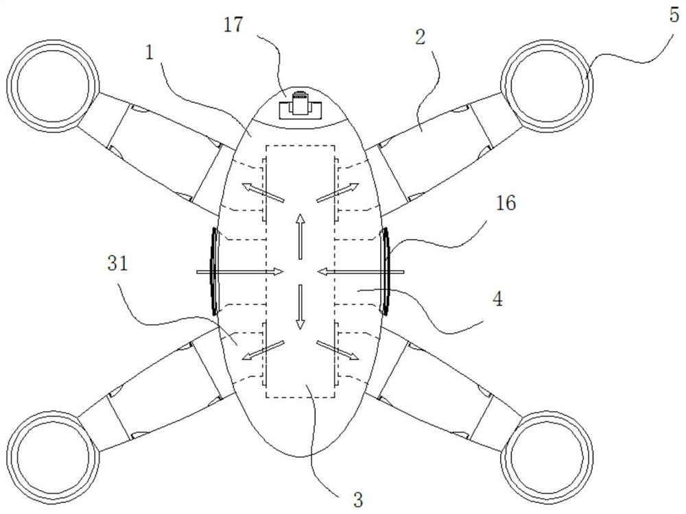
[0037] see figure 1, the invention provides a technical solution: a UAV without rotors, including a fuselage body 1 and four sets of arms 2 arranged around the fuselage body 1 in a ring, and an air intake chamber 3 is arranged inside the fuselage body 1 , the intake chamber 3 has an air inlet 4 connected to both sides of the fuselage body 1, the machine arm 2 is a hollow pipe structure, and the inner end of the machine arm 2 is respectively connected to the air intake chamber 3 through a soft air pipe 31, the machine arm The outer ends of the arms 2 are respectively connected with air jet rings 5 ​​, and each of the four sets of arms 2 is provided with a turbofan 7 driven by a servo motor 6 . When the UAV is working, the four groups of servo motors 6 inside the arms 2 drive the turbofan 7 to rotate at high speed, and the external air is sucked in through the air inlets 4 on both sides of the fuselage. The inner cavity forms an airflow with a certain high flow rate, and the hi...

Embodiment 2

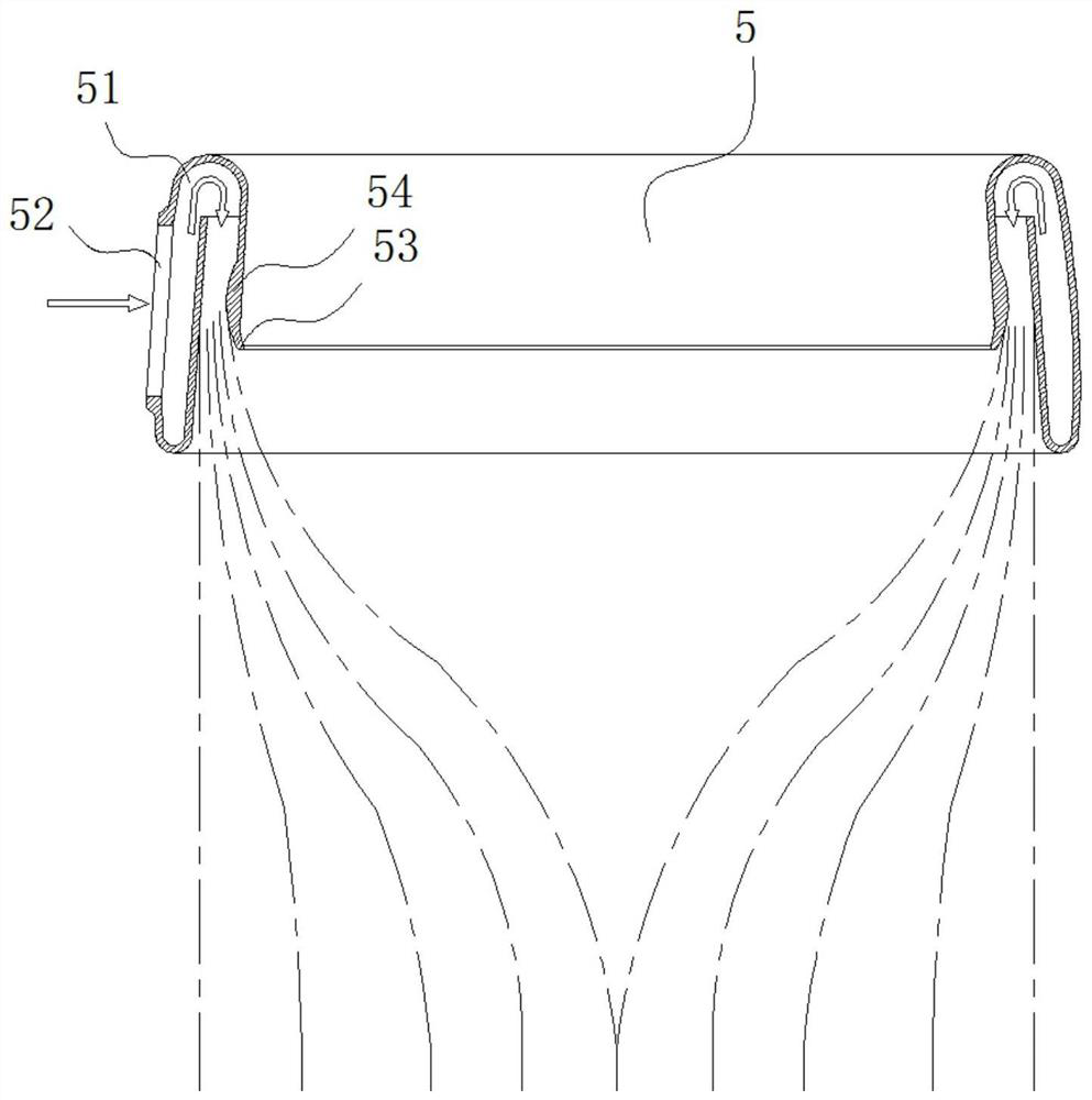
[0039] see figure 2 , on the basis of Embodiment 1, the airflow injection ring 5 is an integrally formed annular structure formed by bending the upper and lower ends of a cylindrical structure with different bending radii to the inner side of the cylinder for 180°. A U-shaped guide channel 51 is formed inside the jet ring 5, and a jet air inlet 52 is provided at the connection between the U-shaped guide channel 51 and the outer end of the machine arm 2, and the annular air outlet port 53 of the U-shaped guide channel 51 is located at the airflow injection ring 5. The middle part of the inner cavity is set in the shape of a horn with rounded corners; since the U-shaped flow guide channel 51 is formed inside the airflow injection ring 5, the air flow has a process of reversing after passing through the U-shaped flow guide channel 51 after being introduced by the machine arm 2. , in the process of airflow reversing at the same time, the circumferential uniform distribution is ca...

Embodiment 3

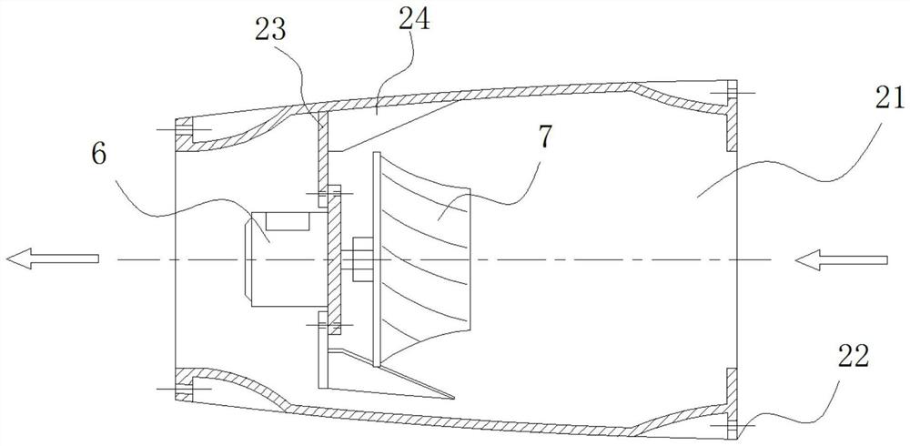
[0041] see Figure 3-4 , on the basis of Embodiment 1, the middle part of the machine arm 2 is a detachable installation section 21, and the two ends of the installation section 21 are connecting flange ends 22 with screw holes, and the inner wall of the installation section 21 is provided with a The extension arm 23 of 6, the inner and outer sides of the servo motor 6 and the turbofan 7 in the adjacent two groups of arms 2 are installed in the opposite direction, so as to offset the reaction torque of the drone during flight and avoid the drone from appearing during the flight. spin case; further, see Figure 5 , the extension arm 23 is provided with three groups distributed in a ring, and a fan-shaped airflow channel is formed between the extension arm 23 and the extension arm 23, which is used to circulate high air flow. The three groups of extension arms 23 are distributed in a spoke-like ring to ensure a stable connection structure At the same time, the number of extensi...


PUM


Abstract

The invention discloses a rotor-free unmanned aerial vehicle in the technical field of unmanned aerial vehicles, the rotor-free unmanned aerial vehicle comprises a vehicle body and four sets of vehicle arms annularly arranged on the periphery of the vehicle body, an air inlet bin is arranged in the vehicle body, the air inlet bin is provided with air inlets communicating to the two sides of the vehicle body, and the vehicle arms are each of a hollow pipe body structure; the inner side ends of the machine arms are communicated with the air inlet bin through soft air pipes, the outer side ends of the machine arms are communicated with airflow jet rings, turbofans driven by servo motors are arranged in the four sets of machine arms respectively, and a battery mainboard bin is arranged at the position, located below the air inlet bin, in the machine body. According to the rotor-free unmanned aerial vehicle, most topographic conditions can be ignored, the unmanned aerial vehicle is different from an unmanned aerial vehicle with external rotor wings, blades are prone to being damaged during flight, the unmanned aerial vehicle is damaged, and the unmanned aerial vehicle with the built-in rotor wings can be ignored from the dangerous factors, so that the unmanned aerial vehicle with the built-in rotor wings is safe and reliable. And the unmanned aerial vehicle has good flight stability, controllability and safety.

Description

technical field [0001] The invention relates to the technical field of drones, in particular to a rotorless drone. Background technique [0002] With the continuous development of science and technology, the application of drones has become more and more comprehensive, and it has become an indispensable part in power inspections and fire inspections. With the development of drone technology, drones have become popular in people's daily life. Taking pictures and photography all bring people a new perspective experience. However, the take-off of drones relies on the high-speed rotating blades to bring lift. If someone approaches and touches the exposed high-speed rotating blades, the consequences will be disastrous. When drones are operating in mountainous areas, drone blades collide with tree branches, and branches and leaves are one of the main reasons for drone crashes. It is not uncommon for the uneven ground and the raised sand and gravel to damage the blades during the...

Claims


Application Information

Patent Timeline
IPC IPC(8): B64C39/02
CPCB64C39/02B64U10/00B64U50/19B64U50/00
Inventor 谢鑫祥陈志超吴敏敏陈火明汤钟敏吴长海周洁罗梁
Owner 国网福建省电力有限公司连城县供电公司
Why Eureka
Try Eureka