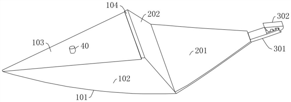
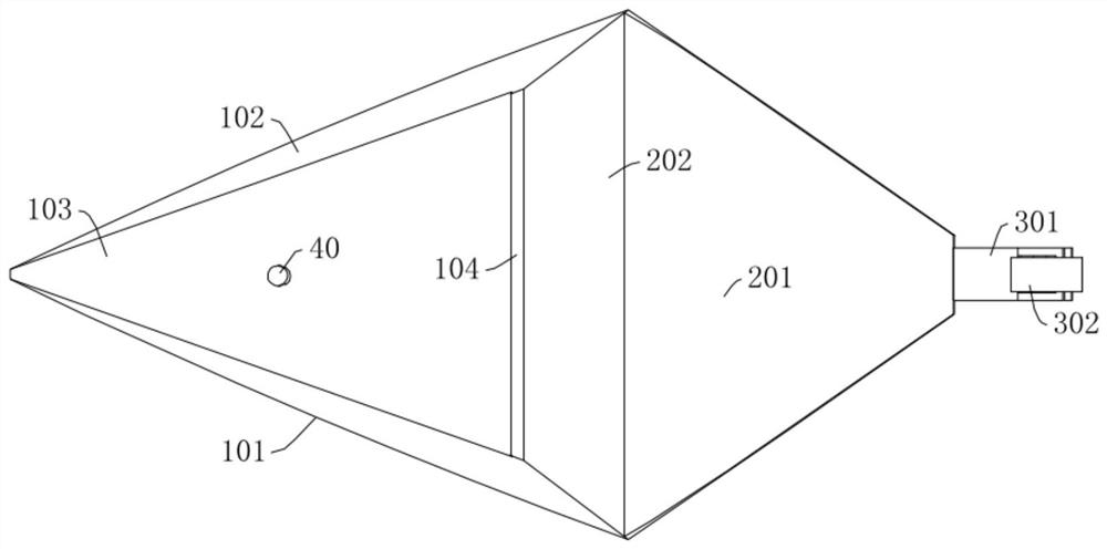
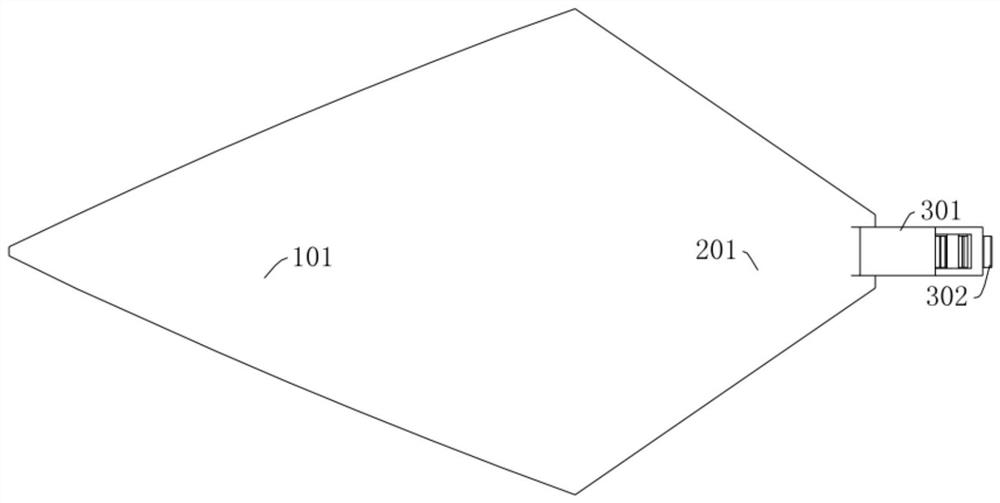
A Hypersonic Inlet Cowling Scheme Using Slit Flow to Realize Separation

A hypersonic, air inlet technology, applied in the combustion of the air inlet of the power unit, the arrangement/installation of the power unit, the power unit on the aircraft, etc., can solve the difficulty of increasing the flight resistance and the thermal protection of the projectile and fairing, etc. problems, to achieve the effect of low structural strength requirements, flexible shape design and small size

Active Publication Date: 2022-06-07
NAT UNIV OF DEFENSE TECH
View PDF9 Cites 0 Cited by
  • Summary
  • Abstract
  • Description
  • Claims
  • Application Information

AI Technical Summary

Problems solved by technology

In order to ensure sufficient separation aerodynamic force and torque, the existing small cover scheme is designed with a relatively large aerodynamic compression surface, and the shock wave generated by the compression surface will cause serious shock wave / boundary layer interference when incident on the projectile wall, which increases the Flight resistance and thermal protection difficulty of projectile body and fairing

Method used


Image

  • A Hypersonic Inlet Cowling Scheme Using Slit Flow to Realize Separation
  • A Hypersonic Inlet Cowling Scheme Using Slit Flow to Realize Separation
  • A Hypersonic Inlet Cowling Scheme Using Slit Flow to Realize Separation

Examples


Embodiment Construction

[0041] The technical solutions in the embodiments of the present invention will be clearly and completely described below with reference to the accompanying drawings in the embodiments of the present invention. Obviously, the described embodiments are only a part of the embodiments of the present invention, not all of the embodiments. Based on the embodiments of the present invention, all other embodiments obtained by those of ordinary skill in the art without creative efforts shall fall within the protection scope of the present invention.

[0042] It should be noted that all directional indications (such as up, down, left, right, front, back, etc.) in the embodiments of the present invention are only used to explain the relationship between various components under a certain posture (as shown in the accompanying drawings). The relative positional relationship, the movement situation, etc., if the specific posture changes, the directional indication also changes accordingly. ...


PUM


Abstract

The invention discloses a scheme for a hypersonic air inlet fairing that utilizes slit flow to realize separation, including a drag reducing unit and a blocking unit, and the blocking unit is provided with a blocking structure capable of blocking the inlet of the air inlet; The head of the drag reducing unit is gathered at one point, the tail of the drag reducing unit is connected to the head of the blocking unit, and the drag reducing unit gradually widens and thickens along the direction from the head to the tail, The tail of the blocking unit is detachably fixedly connected to the bottom outer wall of the air inlet through a first connecting structure; the drag reducing unit is connected to the outer wall of the aircraft through a second connecting structure, and the drag reducing unit is connected to the outer wall of the aircraft through a second connecting structure There are gaps between the outer walls of the aircraft. The separation of the fairing can be achieved by providing the pneumatic separation force provided by the slit flow, which effectively solves the contradiction that the reduction of the resistance of the fairing and ensuring sufficient separation torque cannot be taken into account at the same time.

Description

technical field [0001] The invention relates to the technical field of air inlets of aircraft, in particular to a hypersonic air inlet fairing scheme utilizing slit flow to realize separation. Background technique [0002] The fairing was first proposed for the rocket transport payload to prevent the payload from being affected by external harmful environments such as aerodynamic force, aerodynamic heat and vibration. The common structure is the clam shell type (two halves), which is composed of an end head, a front cone section, a cylinder section, an inverted cone section, and a longitudinal and transverse separation mechanism. [0003] For air-breathing hypersonic vehicles, in order to ensure the normal operation of the hypersonic inlet, other flight platforms are often needed, such as mounted aircraft and booster rockets. The hypersonic vehicle is sent to the designated flight altitude by the flight platform and made to reach the designated initial flight speed. During...

Claims


Application Information

Patent Timeline
Patent Type & Authority Patents(China)
IPC IPC(8): B64D33/02B64D29/06
CPCB64D33/02B64D29/06B64D2033/026Y02T50/40
Inventor 何刚赵一龙赵玉新王振国
Owner NAT UNIV OF DEFENSE TECH
Why Eureka
Try Eureka