Push-pull type transfer robot

A handling robot, push-pull technology, applied in the direction of conveyor objects, transportation and packaging, lifting devices, etc., can solve problems such as low efficiency, equipment coordination hazards, etc., achieve flexible and convenient use, stable and compact overall structure, and increase equipment maintenance and the effect of maintenance space

Active Publication Date: 2021-08-13
SHENYANG SIASUN ROBOT & AUTOMATION
View PDF7 Cites 1 Cited by
  • Summary
  • Abstract
  • Description
  • Claims
  • Application Information

AI Technical Summary

Problems solved by technology

[0002] In the prior art, product transmission in many fields is still done manually. For example, in the field of tire manufacturing, the transmission process of sending tires to designated locations for special treatment is still done by manpower, which is not only inefficient, but also exists in coordination with equipment certain danger

Method used


Image

  • Push-pull type transfer robot
  • Push-pull type transfer robot
  • Push-pull type transfer robot

Examples


Embodiment Construction

[0030] The present invention will be described in further detail below in conjunction with the accompanying drawings.

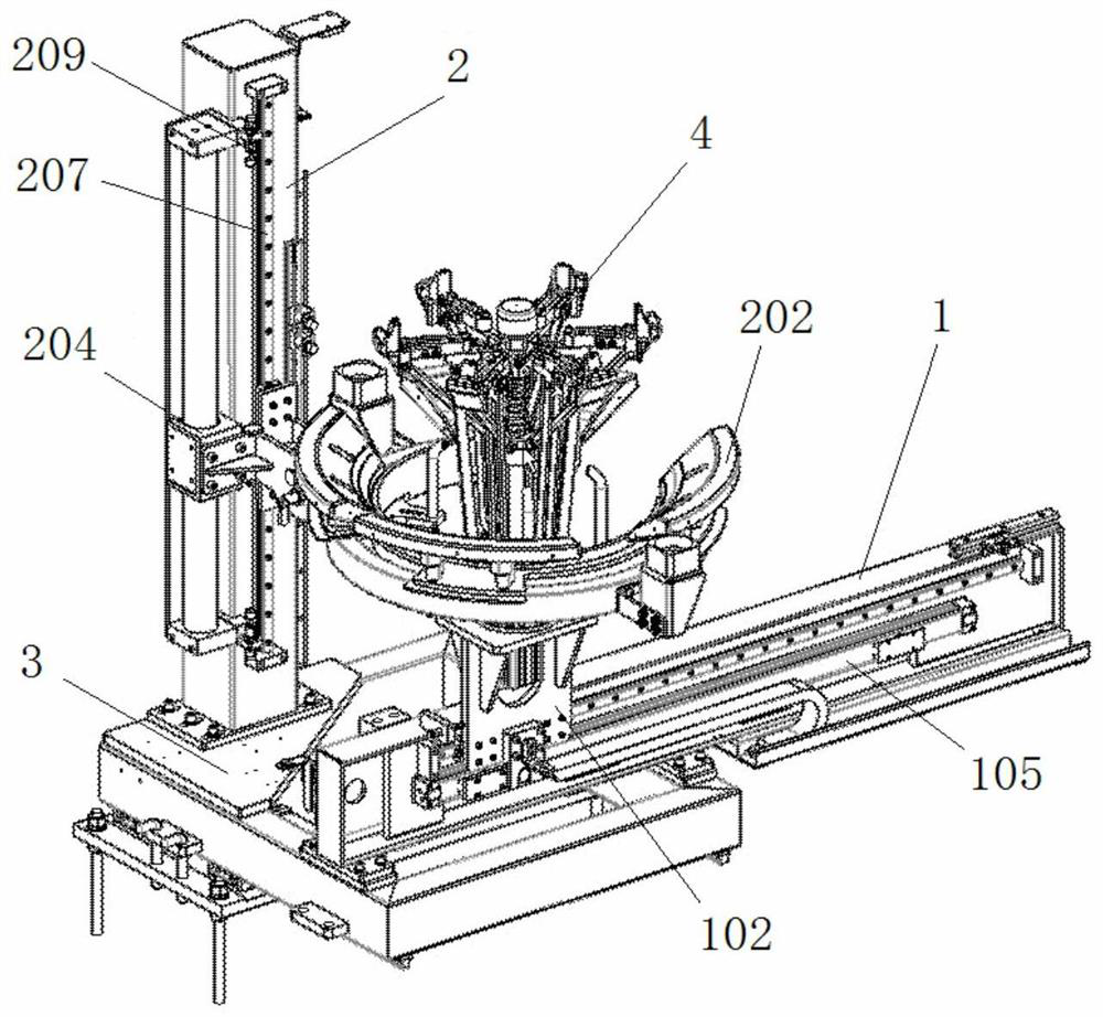
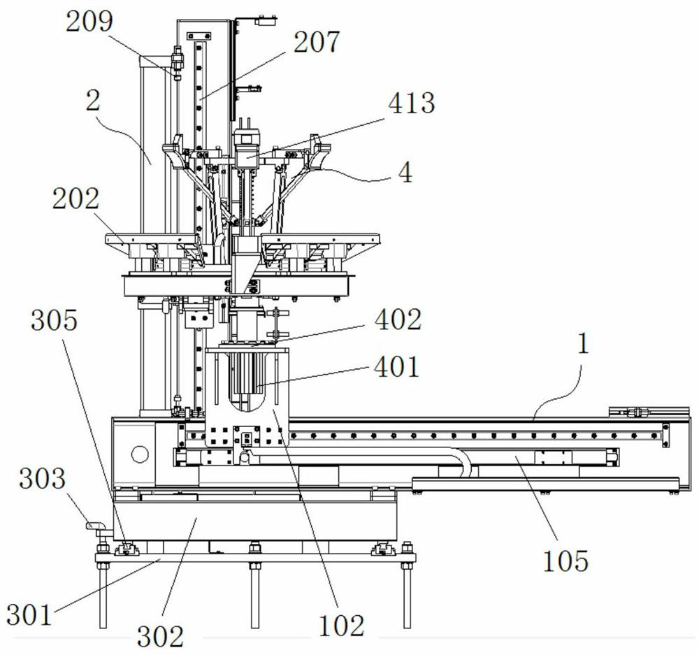
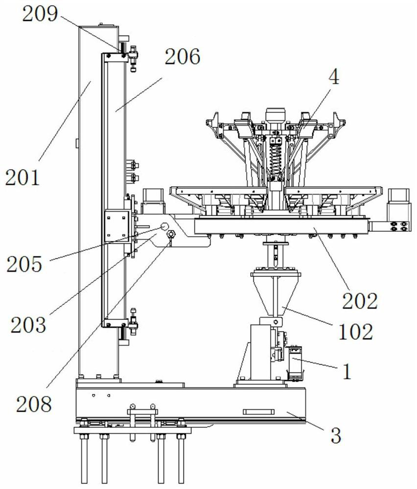
[0031] Such as Figure 1-9 As shown, the present invention includes a base 3, a grip assembly 4, a grip walking mechanism 1 and a cargo lifting mechanism 2, the grip walking mechanism 1 and the cargo lifting mechanism 2 are both arranged on the base 3, and the grip assembly 4 is installed on The gripper walking mechanism 1 is driven to move horizontally by the gripper walking mechanism 1. The cargo lifting mechanism 2 is provided with a cargo tray 202 that can be lifted vertically and has a gap on one side, and the gripper assembly 4 passes through the gripper. The hand traveling mechanism 1 is driven to move out of the loading tray 202 by the gap.

[0032] Such as Figure 1~5 As shown, the grip walking mechanism 1 includes a travel driving cylinder 105, a grip support 102 and a mounting seat 101, wherein the mounting seat 101 is fixed on the base 3, and th...


PUM


Abstract

The invention relates to the technical field of logistics, in particular to a push-pull type transfer robot. The push-pull type transfer robot comprises a base, a gripper assembly, a gripper walking mechanism and a cargo carrying lifting mechanism. The gripper walking mechanism and the cargo carrying lifting mechanism are both arranged on the base, the gripper assembly is driven by the gripper walking mechanism to move horizontally, the cargo carrying lifting mechanism is provided with a cargo carrying disc which can vertically ascend and descend, a gap is formed in one side of the cargo carrying disc, and the gripper assembly is driven by the gripper walking mechanism to output the cargo carrying disc through the gap. According to the push-pull type transfer robot, cargoes can be conveyed to a designated to-be-treated position, the overall structure is stable and compact, the push-pull type transfer robot cannot occupy too much space, and the positioning precision is accurate.

Description

technical field [0001] The invention relates to the technical field of logistics, in particular to a push-pull handling robot. Background technique [0002] In the prior art, product transmission in many fields is still done manually. For example, in the field of tire manufacturing, the transmission process of sending tires to designated locations for special treatment is still done by manpower, which is not only inefficient, but also exists in coordination with equipment Certainly dangerous. In addition, with the continuous development of automation system technology in the logistics field, product delivery has higher and higher requirements for the delivery system, and different industries have different functional requirements for the delivery system. How to meet product delivery requirements in a limited space has become a problem that needs to be solved at present. Contents of the invention [0003] The purpose of the present invention is to provide a push-pull hand...

Claims


Application Information

Patent Timeline
IPC IPC(8): B65G47/90B66F7/00B66F7/28
CPCB65G47/901B66F7/00B66F7/28
Inventor 纪然韩天文李文龙王涵玉李清王永昊王军
Owner SHENYANG SIASUN ROBOT & AUTOMATION
Why Eureka
Try Eureka