
An embedded mesh core type metal powder metallurgy process

A technology of powder metallurgy and metal powder, which is applied in the field of metal powder metallurgy technology with embedded mesh core, can solve the problems of high scrap rate, disintegration of embryo body, low strength, etc., to reduce scrap rate, improve adhesion, connect high intensity effect

Active Publication Date: 2022-04-12
上海懋业铁合金有限公司
View PDF7 Cites 0 Cited by
  • Summary
  • Abstract
  • Description
  • Claims
  • Application Information

AI Technical Summary

Problems solved by technology

[0003] However, the metal products after powder metallurgy often have a problem of low strength. When the metal products are put into use, they are often prone to cracking. changes, it is also easy to cause the embryo body to disintegrate, resulting in a high scrap rate

Method used


Image

  • An embedded mesh core type metal powder metallurgy process
  • An embedded mesh core type metal powder metallurgy process
  • An embedded mesh core type metal powder metallurgy process

Examples


Embodiment 1

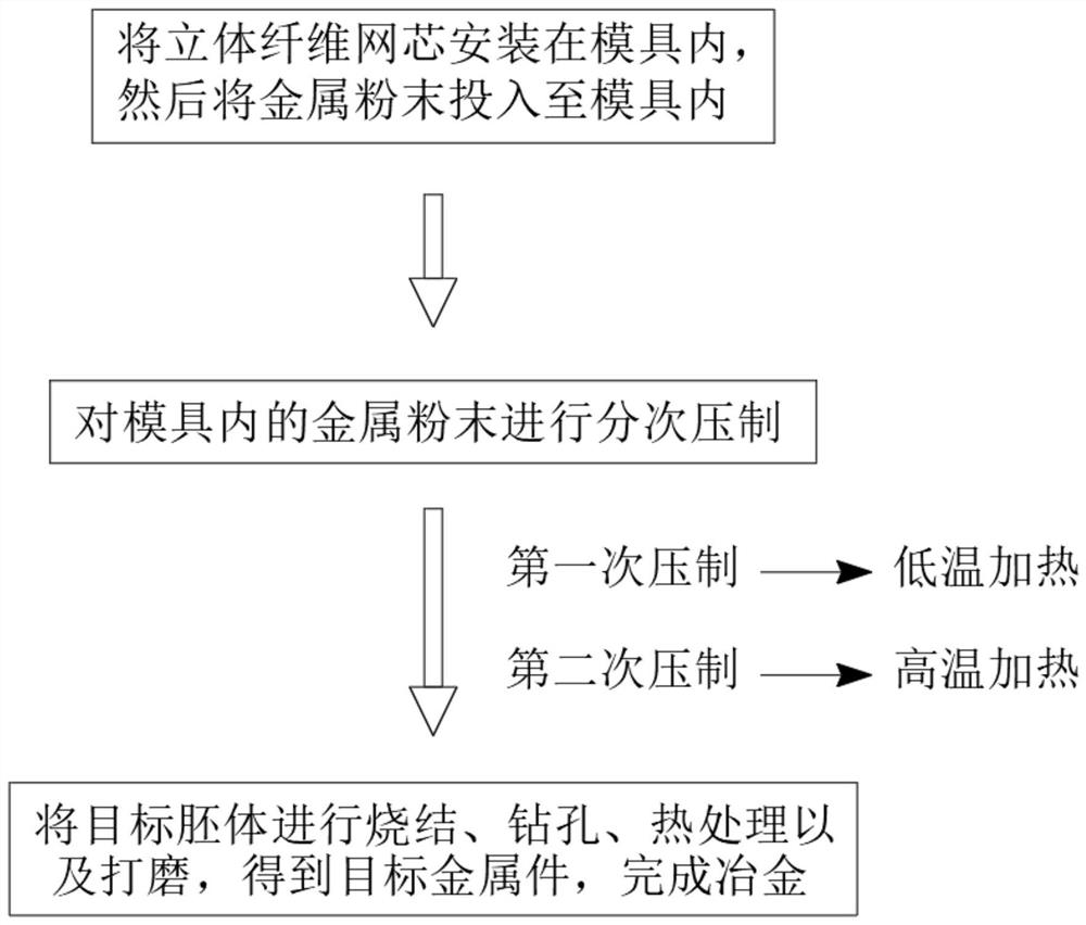
[0048] see figure 1 , an embedded mesh core type metal powder metallurgy process, comprising the following steps:

[0049] S1. First, install the three-dimensional fiber mesh core in a mold with thermal separation holes, and then put metal powder into the mold;

[0050] see Figure 5 , in the figure, a represents the mould, b represents the thermal separation hole, and c represents the hot melt adhesive. The specific steps for installing the three-dimensional fiber mesh core in step S1 are:

[0051] S11. First, insert the end of the heat-off rod of the three-dimensional fiber net core into the heat-off hole on the mold half, and then use hot melt glue to squeeze into the heat-off hole, so that the heat-off rod is glued into the heat-off hole;

[0052] S12. Then align the other half-mold with the thermal release rod on the other side and insert it to complete the installation of the three-dimensional fiber mesh core. The two half-molds form a whole mold for easy demoulding. ...

Embodiment 2

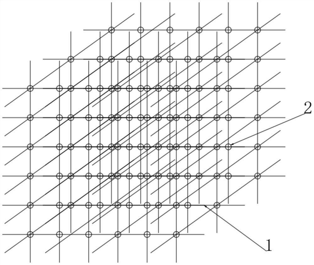
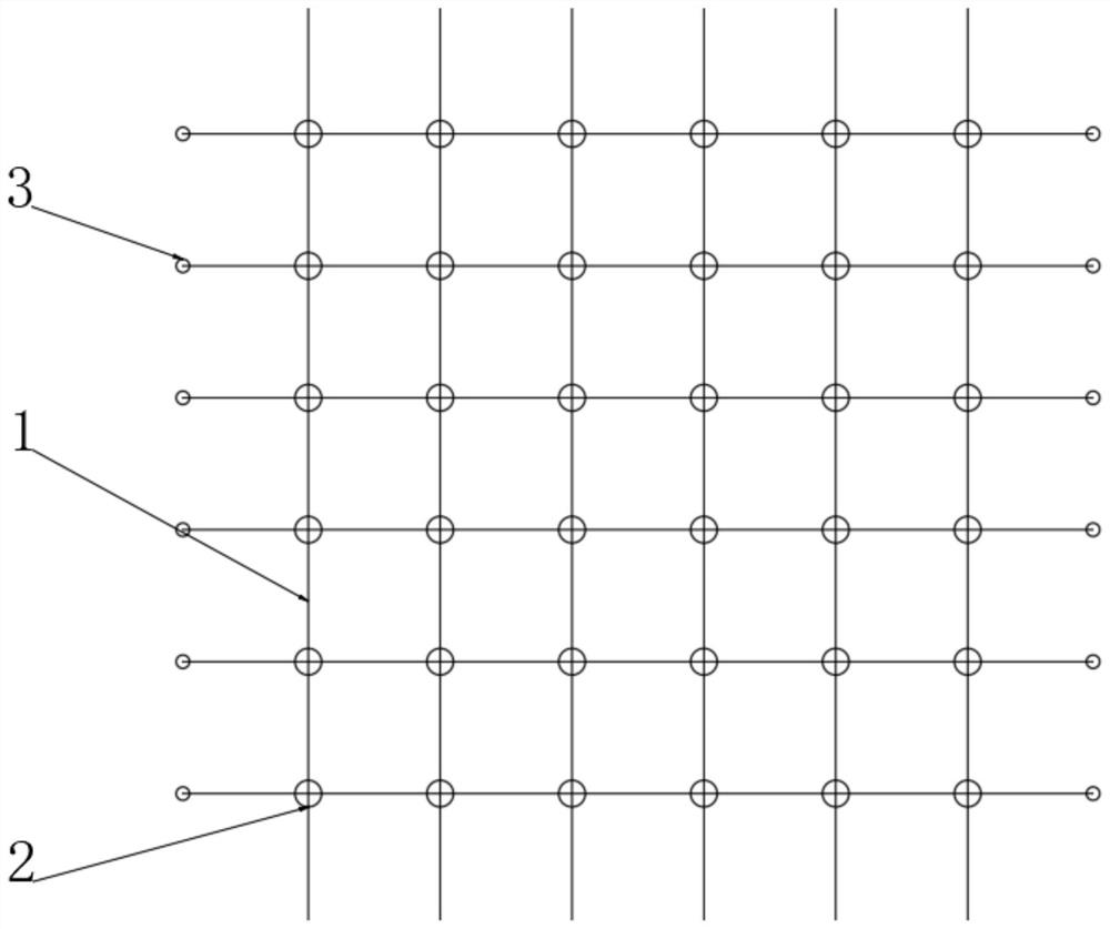
[0061] Compared with Embodiment 1, this embodiment is different in the specific setting structure of the reinforcing ball 2 .

[0062] The reinforcing ball 2 includes an upper sealing hard shell 81 and a lower transparent hard shell 82 fixedly connected to the lower end of the upper sealing hard shell 81, and high temperature resistant liquid glue is filled in the space surrounded by the upper sealing hard shell 81 and the lower transparent hard shell 82 , the lower transparent hard shell 82 is a porous structure, and the lower transparent hard shell 82 is wrapped with a hot-melt layer. The melting point of the hot-melt layer is 90-150°C. The hard shell 82 is transparent, and the high-temperature-resistant liquid glue directly overflows downward under the action of gravity. Compared with the previous setting of the reinforcing ball 2, the structure is simpler.


PUM

PropertyMeasurementUnit
melting pointaaaaaaaaaa
tensile strengthaaaaaaaaaa

Abstract

The invention discloses an embedded mesh core type metal powder metallurgy process, which belongs to the field of powder metallurgy technology. It is an embedded mesh core type metal powder metallurgy process. By installing and embedding a three-dimensional fiber mesh core in a mould, when pressing in stages , under the action of heating, on the one hand, the thermal separation rod is destroyed, so that the three-dimensional fiber mesh core is transferred from the mold to the body, and on the other hand, the glue in the three-dimensional fiber mesh core is overflowed, which significantly improves the adhesion between metal powders Force, so that the embryo body is not easy to disintegrate during sintering, thereby effectively reducing the scrap rate and material waste. At the same time, it can effectively enhance the adhesion between the three-dimensional fiber mesh core and the metal, so that the connection strength of the contact part between the two is higher. , thereby effectively avoiding cracks in the finished product of the target metal part, so that the mechanical properties of the target metal part are significantly enhanced compared with the prior art, and effectively overcome the problem of low strength of the metal part obtained by powder metallurgy in the prior art.

Description

technical field [0001] The invention relates to the field of powder metallurgy technology, and more specifically relates to a metal powder metallurgy technology with embedded mesh core. Background technique [0002] Powder metallurgy is a process technology for producing metal powder or using metal powder (or a mixture of metal powder and non-metal powder) as raw material, forming and sintering to manufacture metal materials, composite materials and various types of products. The powder metallurgy method has similarities with the production of ceramics, and both belong to the powder sintering technology. Therefore, a series of new powder metallurgy technologies can also be used for the preparation of ceramic materials. Due to the advantages of powder metallurgy technology, it has become the key to solve the problems of new materials and plays a pivotal role in the development of new materials. [0003] However, the metal products after powder metallurgy often have a problem...

Claims


Application Information

Patent Timeline
Patent Type & Authority Patents(China)
IPC IPC(8): C22C47/06C22C47/14
CPCC22C47/06C22C47/14
Inventor 吴浩
Owner 上海懋业铁合金有限公司
Learn More