Electrolyzer flow field plate structure

An electrolytic cell and flow field plate technology, which can be applied to electrolytic components, electrolytic processes, cells, etc., can solve problems such as potential safety hazards, electrolyte boiling, and affecting the operating efficiency of electrolytic cells.

Active Publication Date: 2021-09-10
北京华易氢元科技有限公司
View PDF21 Cites 0 Cited by
  • Summary
  • Abstract
  • Description
  • Claims
  • Application Information

AI Technical Summary

Problems solved by technology

However, the temperature difference between the electrolyte outlet and the electrolyte inlet is still very large, which makes the temperature distribution of the end plate of the electrolytic cell uneven, and the temperature of the electrolyte flowing out of the electrolyte outlet needs to be further cooled before it can be reused, which affects the operating efficiency of the electrolyzer; The problem of electrolyte boiling is prone to occur, which poses a safety hazard

Method used


Image

  • Electrolyzer flow field plate structure
  • Electrolyzer flow field plate structure

Examples


Embodiment Construction

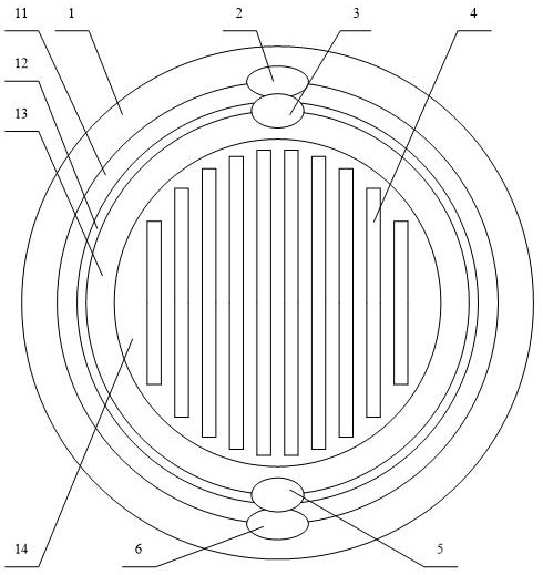
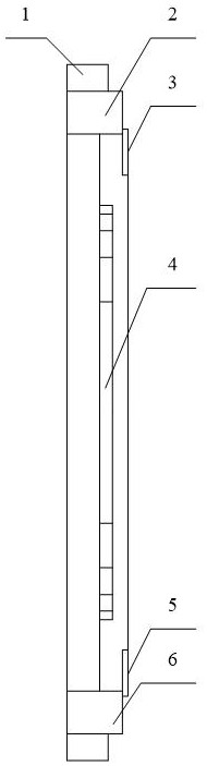
[0033] The invention discloses a flow field plate structure of an electrolyzer, which improves the operating efficiency of the electrolyzer and eliminates potential safety hazards.

[0034] The following will clearly and completely describe the technical solutions in the embodiments of the present invention with reference to the accompanying drawings in the embodiments of the present invention. Obviously, the described embodiments are only some, not all, embodiments of the present invention. Based on the embodiments of the present invention, all other embodiments obtained by persons of ordinary skill in the art without making creative efforts belong to the protection scope of the present invention.

[0035] Such as figure 1 and figure 2 As shown, the embodiment of the present invention provides an electrolytic cell flow field plate structure, including: an electrolytic cell end plate 1; an electrolyte outlet 2 disposed on the electrolytic cell end plate 1; an electrolyte inl...


PUM


Abstract

The invention discloses an electrolytic cell flow field plate structure, comprising: an electrolytic cell end plate (1); an electrolyte outlet (2) arranged on the electrolytic cell end plate (1); an electrolytic cell end plate arranged on the electrolytic cell end plate The electrolyte inlet (6) on (1), the electrolyte outlet (2) and the electrolyte inlet (6) are arranged symmetrically; the heat pipe (4) arranged on the end plate of the electrolytic cell (1), the heat pipe The condensation section of (4) is close to the electrolyte inlet (6), and the evaporation section of the heat pipe (4) is close to the electrolyte outlet (2). The flow field plate structure of the electrolytic cell provided by the present invention effectively reduces the temperature difference between the electrolyte outlet and the electrolyte inlet, improves the uniform distribution of the temperature on the end plate of the electrolytic cell, increases the electrolysis temperature, and effectively improves the operation of the electrolytic cell Efficiency: The temperature of the electrolyte outlet is effectively reduced, thereby avoiding the problem of electrolyte boiling at the electrolyte outlet and eliminating potential safety hazards.

Description

technical field [0001] The invention relates to the technical field of electrolyzer flow field plate structure equipment, in particular to an electrolyzer flow field plate structure. Background technique [0002] Hydrogen energy plays an important role in future energy development. Hydrogen production from renewable energy combined with water electrolysis will play an important role in the future. With the continuous expansion of the scale of the electrolytic cell, the increase in the number of electrolytic cells and the increase in the size of the end plate of the electrolytic cell makes it difficult to evenly distribute the electrolyte, which intensifies the temperature inhomogeneity inside the electrolytic cell. [0003] According to the research, increasing the electrolysis temperature can effectively improve the electrolysis efficiency (for example, it has been confirmed in the existing process that the electrolysis efficiency increases by about 1~2% when the temperatu...

Claims


Application Information

Patent Timeline
Patent Type & Authority Patents(China)
IPC IPC(8): C25B9/70C25B9/19C25B9/67C25B15/08C25B1/04
CPCC25B1/04C25B15/08Y02E60/36
Inventor 史翊翔刘梦华龚娅李爽蔡宁生
Owner 北京华易氢元科技有限公司
Why Eureka
Try Eureka