Fault diagnosis method, device and equipment for pressure sensor and storage medium

A technology of pressure sensor and fault diagnosis, which is applied to measuring devices, measuring fluid pressure, instruments, etc., and can solve problems such as low efficiency

Active Publication Date: 2021-08-13
WUHAN FINEMEMS
View PDF11 Cites 0 Cited by
  • Summary
  • Abstract
  • Description
  • Claims
  • Application Information

AI Technical Summary

Problems solved by technology

Taking the gold wire bonding process as an example, in the prior art, one is to manually complete the gold wire bonding, and the bonding quality is observed manually after the bonding is completed, which is inefficient; the other is that the bonding machine automatically completes the bonding and roughly Judgment (connection or not), and then assist manual observation of the bonding quality, the bonding machine only roughly judges during the bonding process, but cannot detect the neck sagging after the bonding is completed, that is, it needs to be manually reassessed after the bonding is completed. inspection, low efficiency

Method used


Image

  • Fault diagnosis method, device and equipment for pressure sensor and storage medium
  • Fault diagnosis method, device and equipment for pressure sensor and storage medium
  • Fault diagnosis method, device and equipment for pressure sensor and storage medium

Examples


Embodiment Construction

[0062] It should be understood that the specific embodiments described here are only used to explain the present invention, not to limit the present invention.

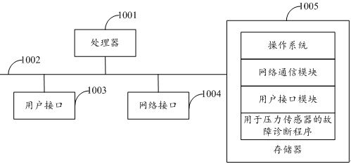
[0063] refer to figure 1 , figure 1 It is a structural schematic diagram of a fault diagnosis device for a pressure sensor in the hardware operating environment involved in the solution of the embodiment of the present invention.

[0064] Such as figure 1 As shown, the fault diagnosis device for pressure sensors may include: a processor 1001 , such as a central processing unit (Central Processing Unit, CPU), a communication bus 1002 , a user interface 1003 , a network interface 1004 , and a memory 1005 . Wherein, the communication bus 1002 is used to realize connection and communication between these components. The user interface 1003 may include a display screen (Display), an input unit such as a keyboard (Keyboard), and the optional user interface 1003 may also include a standard wired interface and a wireless int...


PUM


Abstract

The invention discloses a fault diagnosis method and device for a pressure sensor, equipment and a storage medium. The fault diagnosis method for the pressure sensor comprises the following steps: acquiring a first image in a first direction in real time through a micro image device, wherein the micro image device is arranged in the pressure sensor; according to the first image, determining a contour image of a to-be-evaluated object; performing region division on the contour image according to a preset region division rule; and judging whether the to-be-evaluated object has defects or not according to the contour image after region division.

Description

technical field [0001] The invention relates to the technical field of pressure sensors, in particular to a fault diagnosis method, device, equipment and storage medium for pressure sensors. Background technique [0002] The processing of traditional pressure sensors usually includes cleaning, patching, gold wire bonding and other processes. Taking the gold wire bonding process as an example, in the prior art, one is to manually complete the gold wire bonding, and the bonding quality is observed manually after the bonding is completed, which is inefficient; the other is that the bonding machine automatically completes the bonding and roughly Judgment (connection or not), and then assist manual observation of the bonding quality, the bonding machine only roughly judges during the bonding process, but cannot detect the neck sagging after the bonding is completed, that is, it needs to be manually reassessed after the bonding is completed. Inspection, low efficiency. [0003] ...

Claims


Application Information

Patent Timeline
Patent Type & Authority Applications(China)
IPC IPC(8): G01N21/88G01L25/00G01L27/00G06T7/00G06T7/13G06T7/62
CPCG01L25/00G01L27/007G01N21/8851G01N2021/8887G06T7/0004G06T2207/10004G06T2207/30108G06T7/13G06T7/62
Inventor 王小平曹万梁世豪洪鹏
Owner WUHAN FINEMEMS
Why Eureka
Try Eureka