Bistable electromagnetic system applied to contactor and contactor thereof

An electromagnetic system and bistable technology, applied in the direction of electromagnetic relays, electromagnetic relay details, circuits, etc., can solve the problems of complex structural design of electromagnetic systems, many assembly parts, high material costs, etc., to improve performance and market competition Power, short energization time, and reduced volume

Pending Publication Date: 2021-08-13
ZHEJIANG TENGEN ELECTRIC
View PDF1 Cites 0 Cited by
  • Summary
  • Abstract
  • Description
  • Claims
  • Application Information

AI Technical Summary

Problems solved by technology

[0006] The technical problem to be solved by the present invention is to overcome the complex design of the electromagnetic system structure of the double magnetic steel structure in the prior art, which requires two permanent magnets, many assembly parts, high material cost, cumbersome installation, and low assembly efficiency , the problem of high manufacturing cost, so as to provide a bistable electromagnetic system applied to contactors and its contactors with simple structure, convenient installation, cost reduction, and bistable magnetic holding function.

Method used


Image

  • Bistable electromagnetic system applied to contactor and contactor thereof
  • Bistable electromagnetic system applied to contactor and contactor thereof
  • Bistable electromagnetic system applied to contactor and contactor thereof

Examples


Embodiment 1

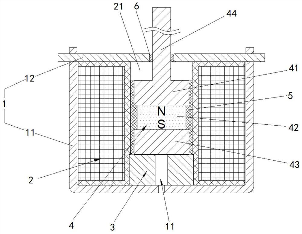
[0040] This embodiment provides as Figure 1-5 A bistable electromagnetic system applied to a contactor is shown, comprising: a yoke frame 1 with a closed installation space;

[0041] The coil structure 2 is installed in the installation space, and includes a middle cavity 21 extending along its axial direction, and the two ends of the middle cavity 21 are respectively limited to the upper and lower ends of the yoke frame 1;

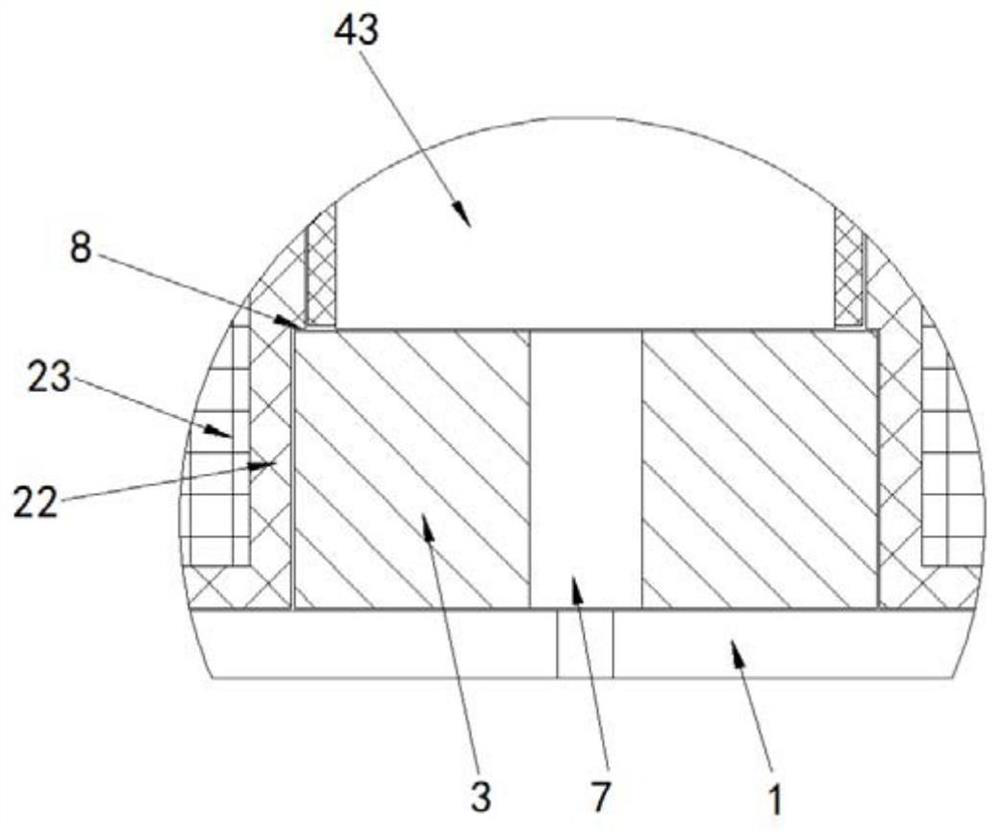
[0042] The magnetic pole 3 is fixed in the middle cavity 21 and connected with the lower end of the yoke frame 1;

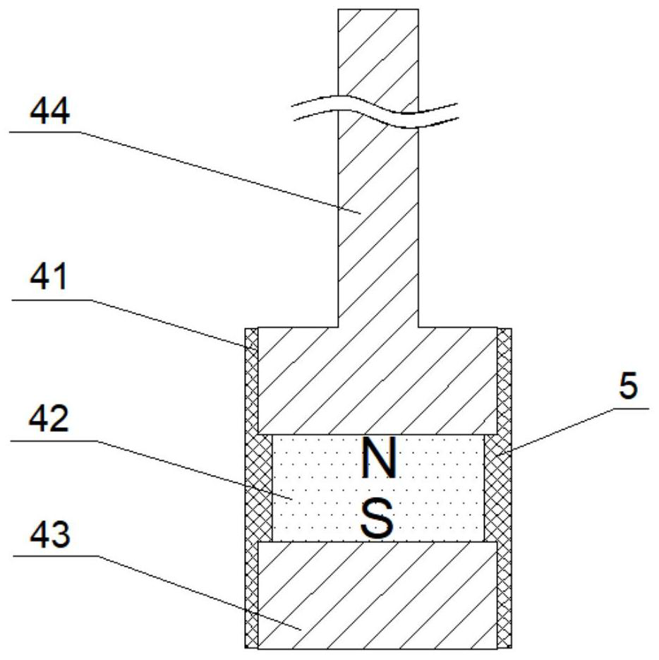
[0043] The moving iron core assembly 4 is movably arranged in the middle cavity 21, and it includes an upper iron core 41, a permanent magnet 42 and a lower iron core 43 which are successively connected along the axial direction of the middle cavity 21, and the upper iron core 41. The permanent magnet 42 and the lower iron core 43 are integrally formed by injection molding. The upper iron core 41 has a drive rod 44 extending out of the upp...

Embodiment 2

[0055]This embodiment provides a contactor, including the bistable electromagnetic system applied to the contactor described in Embodiment 1. The contactor of this embodiment is provided with the above-mentioned bistable electromagnetic system, which naturally has All the advantages brought by the above-mentioned bistable electromagnetic system, the bistable electromagnetic system is connected with the moving contact assembly of the contactor through the driving rod 44 of the moving iron core assembly 4, and plays the role of transmitting motion and force between the two , when the moving iron core assembly 4 moves up and down in the coil structure 2, the contact and separation of the moving contact assembly and the static contact assembly are realized, the response speed is fast, the noise is low, the power consumption is low, and the performance and performance of the contactor are improved. electrical life.


PUM


Abstract

The invention discloses a bistable electromagnetic system applied to a contactor and the contactor thereof. The bistable electromagnetic system comprises a yoke iron shell frame, a coil structure, a magnetic pole and a movable iron core assembly; the magnetic pole is fixed in a middle cavity of the coil structure, and the movable iron core assembly comprises an upper iron core, a permanent magnet and a lower iron core which are connected into a whole and arranged in the middle cavity; and the upper iron core is provided with a driving rod penetrating out of the upper end portion of the yoke iron shell frame, and the driving rod is connected with a moving contact assembly of the contactor. The electromagnetic system adopting the technical scheme has a bistable magnetic holding function and is good in vibration resistance, the coil structure can work by adopting a positive and negative pulse excitation mode, the power-on time is short, the response speed is high, and the power consumption of the coil structure can be greatly reduced. The electromagnetic system is simpler in structural design, convenient to form and manufacture, high in assembly efficiency, beneficial to reducing the size of the electromagnetic system, stable in product performance and capable of reducing the production cost, and thus the use performance and the market competitiveness of the contactor are improved.

Description

technical field [0001] The invention relates to the technical field of low-voltage electrical appliances, in particular to a bistable electromagnetic system applied to a contactor and the contactor thereof. Background technique [0002] The electromagnetic system of traditional AC and DC contactors is mainly composed of moving iron core, static iron core, reaction force spring, contact spring and coil. From the working principle of the contactor, it can be seen that the coil must be continuously energized after closing to keep the moving iron core in the closing state, that is, the maintenance of the moving iron core closing position is at the cost of energy consumption, which consumes electric energy. Large, when the contactor is closed, it will also produce a large working noise, and inevitably generate contact bounce, which reduces the electrical life of the contactor. [0003] With the rapid development of low-voltage electrical appliances, the market has higher and hig...

Claims


Application Information

Patent Timeline
Patent Type & Authority Applications(China)
IPC IPC(8): H01H50/02H01H50/16H01H50/18H01H50/54
CPCH01H50/02H01H50/16H01H50/18H01H50/54
Inventor 李刚何金垚计新华周良王小英金显将苏国俊许浩薛豪王晨
Owner ZHEJIANG TENGEN ELECTRIC
Why Eureka
Try Eureka