Anti-disturbance wear-resistant magnetic stirrer and use method thereof
A magnetic stirring and wear-resistant technology, applied in chemical instruments and methods, mixers, dissolution, etc., can solve the problems of broken coupling, failure, and wear of the magnetic stirrer shell, so as to reduce stop rotation or beating, and is highly applicable The effect of durability and long service life
- Summary
- Abstract
- Description
- Claims
- Application Information
AI Technical Summary
Problems solved by technology
Method used
Image
Examples
Embodiment 1
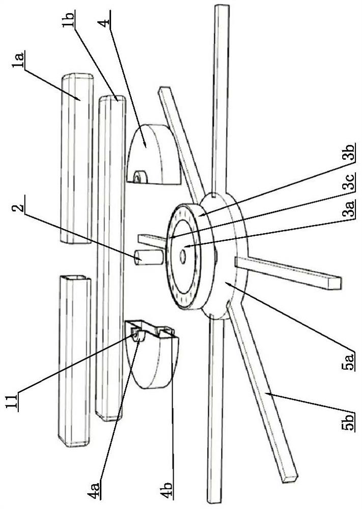
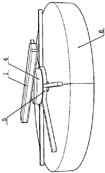
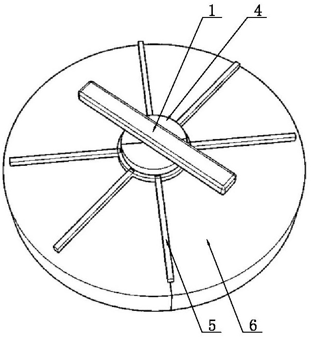
[0037] Such as Figure 1-6 As shown, the anti-disturbance and wear-resistant magnetic stirrer of this embodiment includes a rotor body 1, a first ceramic shaft 2, a plastic bearing 3, a bearing protection shell 4, a flexible base 5, and a magnetic field reconstruction module 6; the rotor body 1 includes a plastic shell 1a, which is composed of two left-right symmetrical shells; a magnet 1b is arranged inside the plastic shell 1a, and the magnet 1b is in the shape of a strip, and a rotating shaft installation hole is opened in the center of the bottom of the plastic shell 1a. Vertically arranged, the upper end of the first ceramic shaft 2 is correspondingly inserted into the shaft installation hole and has an interference fit with the shaft installation hole; the plastic bearing 3 includes a coaxial inner ring body 3a and an outer ring body 3b, and the inner ring body 3a and the outer ring body A number of glass balls 3c are evenly distributed along the circumferential directio...
Embodiment 2
[0050] Such as Figure 7-8 As shown, the difference from Example 1 is that the magnet 1b is strip-shaped, the left and right ends of the plastic casing 1a of the rotor main body 1 are slidably connected with movable sleeves 16, and the front and rear sides of the plastic casing 1a of the rotor main body 1 are both A fixed rod 17 is fixed by a buckle, and the inward end of the fixed rod 17 is connected with the middle part of the plastic casing 1a of the rotor body 1, and the outward end of the fixed rod 17 is slidably connected with a movable sleeve 2 18, and the movable sleeve 18 is connected with the movable sleeve One 16 is vertical, and the left and right sides of movable sleeve 2 18 and movable sleeve 1 16 are arranged in sequence along the length direction to be provided with a number of inclined guide fins 19, and the guide fins 19 on the left and right sides of each movable sleeve are symmetrically arranged. The inclination angle between the guide fins 19 and the corre...
Embodiment 3
[0052] Such as Figure 9 As shown, the difference from Embodiment 1 is that: the bottom surface of the reinforcement support bar 5b and the center base 5a are located in the same plane, and several groups of circumferential reinforcement components radially distributed outwards are arranged on the flexible base 5, The circumferential reinforcement assembly includes several arc-shaped reinforcement connecting bars 13 arranged between any two circumferentially adjacent reinforcing support bars 5b, and the reinforcing connecting bars 13 are made of rubber or silica gel. Reinforcing the connecting strip 13 can further improve the grip stability of the flexible base 5 and prevent the flexible base 5 from shaking.
PUM
 Abstract
Description
Claims
Application Information
 - R&D
- Intellectual Property
- Life Sciences
- Materials
- Tech Scout
- Unparalleled Data Quality
- Higher Quality Content
- 60% Fewer Hallucinations
Browse by: Latest US Patents, China's latest patents, Technical Efficacy Thesaurus, Application Domain, Technology Topic, Popular Technical Reports.
© 2025 PatSnap. All rights reserved.Legal|Privacy policy|Modern Slavery Act Transparency Statement|Sitemap|About US| Contact US: help@patsnap.com


