
A portable numerical control machine tool state monitoring device

A state monitoring device, a technology of numerically controlled machine tools, applied in measuring/indicating equipment, metal processing mechanical parts, metal processing equipment, etc. range, efficient access, ease of transport and handling

Active Publication Date: 2022-08-05
吉林大学重庆研究院
View PDF7 Cites 0 Cited by
  • Summary
  • Abstract
  • Description
  • Claims
  • Application Information

AI Technical Summary

Problems solved by technology

[0003] Although the state monitoring equipment currently used for CNC machine tools can perform state monitoring, there are obvious deficiencies in the aspects of adaptive fixed installation, starting angle adjustment, and displacement angle adjustment. Therefore, a portable CNC machine tool state monitoring device is proposed.

Method used


Image

  • A portable numerical control machine tool state monitoring device
  • A portable numerical control machine tool state monitoring device
  • A portable numerical control machine tool state monitoring device

Examples


Embodiment 1

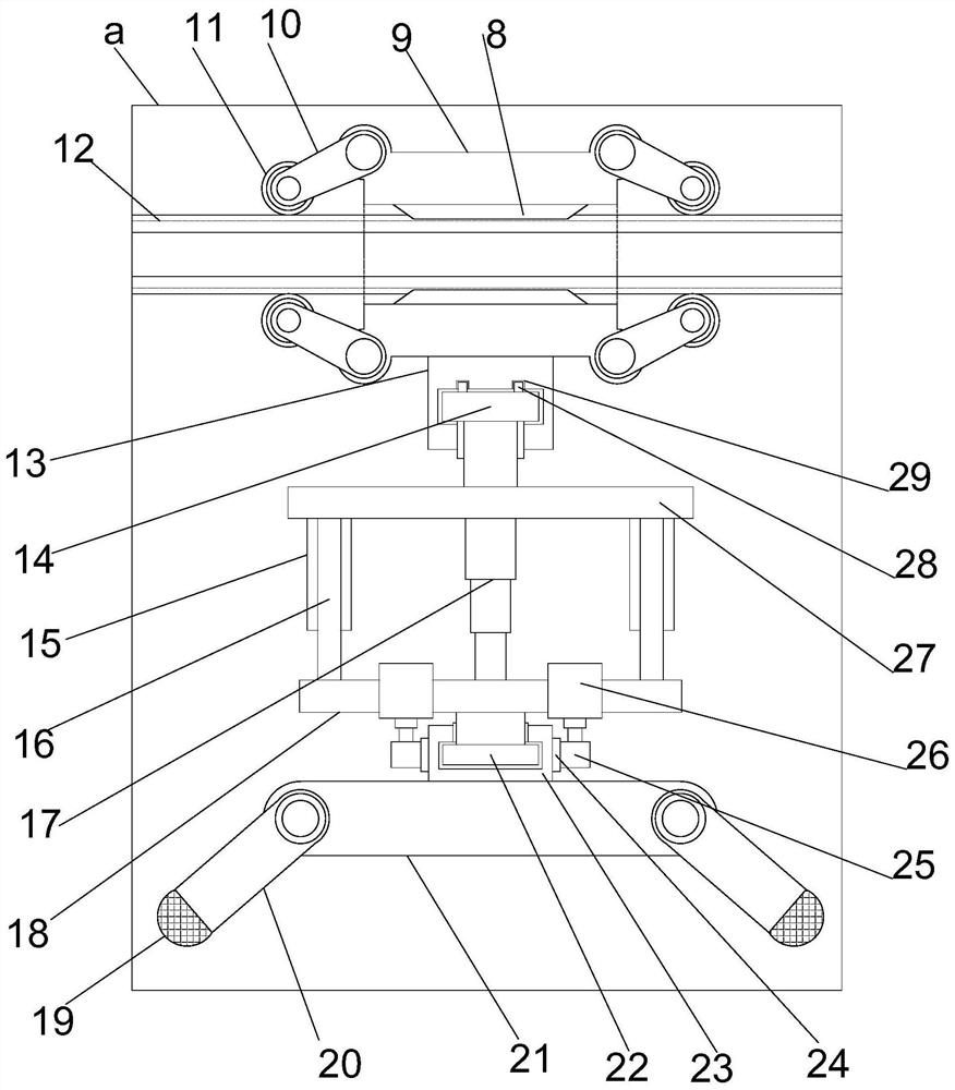
[0028] see Figures 1 to 4 , In the embodiment of the present invention, a portable numerical control machine tool state monitoring device includes a support and installation column 6, and also includes: two sets of rotating telescopic and fixed modules are respectively arranged at both ends of the support and installation column 6; and the rotating and telescopic fixing modules pass through the The positioning and installation structure is connected with the support and installation column 6 ; the displacement monitoring module is moved and movably installed on the support and installation column 6 .

[0029] The moving displacement monitoring module includes a displacement installation cylinder 9, which is movably installed on the support installation column 6, and a sliding conductive column 8 is symmetrically arranged on the inner side of the displacement installation cylinder 9, and the outer side of the support installation column 6 is matched with each other. The slidin...

Embodiment 2

[0032] On the basis of the first embodiment, the rotating telescopic fixing module includes a swing fixing plate 2 , one side of the swing fixing plate 2 is provided with an anti-skid layer 1 , and the other side of the swing fixing plate 2 is provided with a rotating motor 4 through a supporting shaft 3 , the outer end of the rotating motor 4 is provided with an electrically controlled telescopic column 5 through the rotating shaft.

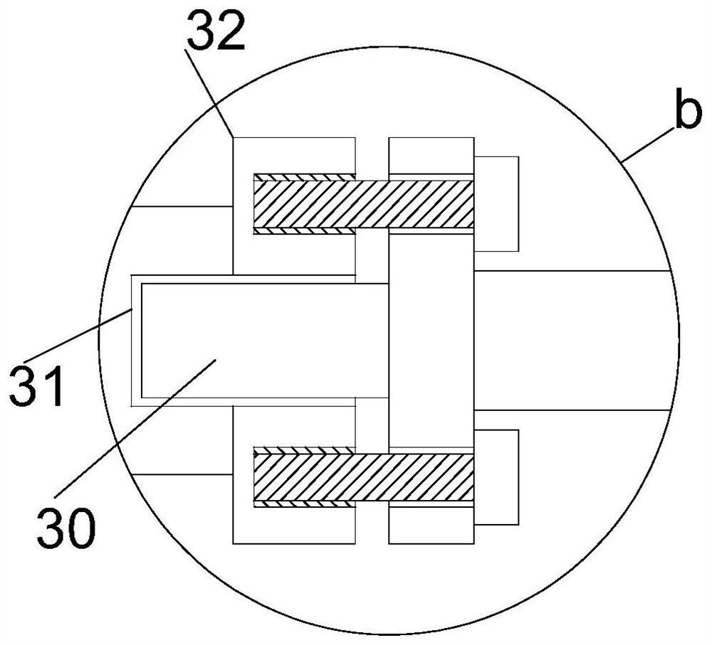
[0033] The positioning and mounting structure includes a fixed mounting plate 32 which is arranged facing each other. The fixed mounting plate 32 is respectively arranged on the electrically controlled telescopic column 5 and the supporting mounting column 6, and a positioning mounting column 30 is arranged in the middle of the fixed mounting plate 32 on one side. The fixed mounting plate 32 on the other side cooperates with the positioning mounting post 30 and is provided with positioning mounting holes 31 . The opposite fixed mounting plate 32 is...

Embodiment 3

[0036] On the basis of the second embodiment, the monitoring sensor 19 may be CSM-EKL3, CSM-SL3, etc.;

[0037] The anti-skid layer 1 can be a rubber layer, resin, etc.;

[0038] The energy storage member 7 may be a battery, a fuel generator, or the like.


PUM


Abstract

The invention relates to the field of numerical control machine tool monitoring, in particular to a portable numerical control machine tool state monitoring device, comprising a support and installation column, and further comprising: two sets of rotating telescopic and fixed modules, which are respectively arranged at both ends of the support and installation column; The positioning and installation structure is connected to the support and installation column; the displacement monitoring module is moved and installed on the support and installation column. The combined positioning and installation structure makes the device easy to transport and load and unload. , so that the device can not only adapt to the installation of CNC machine tools with different internal structures, but also can adjust the initial angle. Through multi-axis rotation adjustment and height adjustment, multi-angle monitoring operations can be realized, and displacement can be realized under the action of guiding movement, which further improves the The monitoring range enables the device to efficiently obtain the status of the CNC machine tool.

Description

technical field [0001] The invention relates to the field of numerical control machine tool monitoring, in particular to a portable numerical control machine tool state monitoring device. Background technique [0002] CNC machine tools are the material and technical basis for composing and equipping modern manufacturing systems, and an important part of industrial intelligence. The purpose of CNC machine tool status monitoring is to grasp the abnormal signs and deterioration information before the failure of the machine tool, which is the basis for the failure of CNC machine tools. Application work such as pattern recognition, fault prediction, fault diagnosis and predictive maintenance provides basic data, enabling targeted measures to be taken before faults occur, and from post-maintenance to predictive maintenance, thereby reducing maintenance costs and improving machine tool efficiency. . Condition monitoring of CNC machine tools usually focuses on the transmission chai...

Claims


Application Information

Patent Timeline
Patent Type & Authority Patents(China)
IPC IPC(8): B23Q17/00
CPCB23Q17/00
Inventor 何佳龙张微李国发王继利田海龙
Owner 吉林大学重庆研究院
Learn More