Air-blast quenching device in extrusion forming process

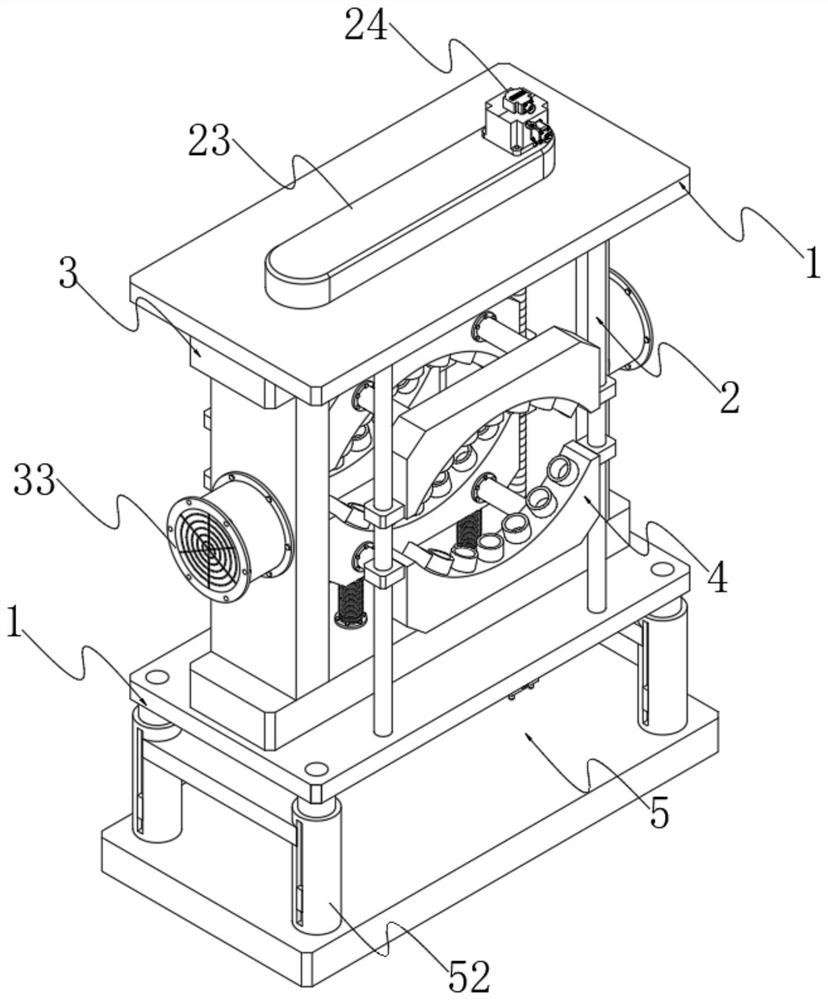
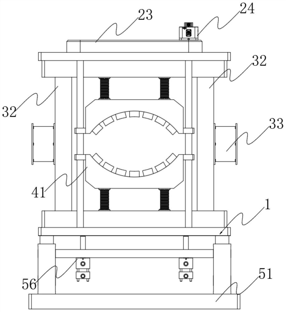
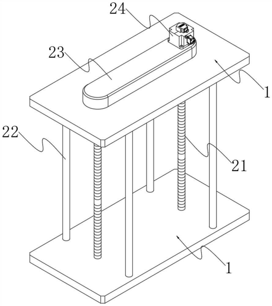
A technology of extrusion molding and quenching device, applied in the direction of quenching device, furnace type, furnace, etc., can solve the problems of limited wind effect, inability to adjust the air outlet, and no height adjustment, so as to facilitate extrusion molding and improve The effect of processing quality and good cooling effect

Inactive Publication Date: 2021-08-17
湖北蓝华铝业有限公司
View PDF5 Cites 0 Cited by
  • Summary
  • Abstract
  • Description
  • Claims
  • Application Information

AI Technical Summary

Problems solved by technology

[0003] At present, in the process of extruding metal products, it is necessary to use air-cooling and quenching to process the extruded parts, but the existing air-cooling and quenching equipment has the following defects in use: On the one hand, different The size of the die hole of the mold is different, and the size of the extruded part is different during extrusion molding, while the distance between the air outlet of the existing air-cooled quenching equipment and the extruded part is fixed, so When performing air-cooling and quenching on extrusions of different sizes, the air outlet cannot be adjusted to a suitable distance from the extrusion, which makes the effect of wind force limited and affects the effect of air-cooling and quenching; on the other hand, the existing The air-cooled quenching equipment does not have the function of height adjustment, and the die holes of different molds have different horizontal heights, which leads to the air-cooled quenching equipment not being able to cool the extrusion better. In view of this, we propose a Air-cooled quenching device during extrusion molding

Method used


Image

  • Air-blast quenching device in extrusion forming process
  • Air-blast quenching device in extrusion forming process
  • Air-blast quenching device in extrusion forming process

Examples


Embodiment Construction

[0034] Next, the technical solutions in the embodiments of the present invention will be apparent from the embodiment of the present invention, and it is clearly described, and it is understood that the described embodiments are merely embodiments of the present invention, not all of the embodiments. Based on the embodiments of the present invention, there are all other embodiments obtained without making creative labor without making creative labor premises.

[0035] In the description of the invention, it is to be understood that the terms "center", "longitudinal", "horizontal", "length", "width", "thickness", "upper", "under", "front", " After "," left "," right "," vertical "," horizontal "," top "," bottom "," inside "," outside "," clockwise "," counterclockwise "or other indication or The positional relationship is based on the orientation or positional relationship shown in the drawings, which is intended to facilitate the description of the present invention and simplifie...


PUM


Abstract

The invention relates to the technical field of air-blast quenching equipment, in particular to an air-blast quenching device in the extrusion forming process. The air-blast quenching device comprises two symmetrical bases. According to the air-blast quenching device in the extrusion forming process, a position adjusting mechanism, an air conveying mechanism and an air-blast quenching mechanism are arranged, a plurality of exhaust ports in the upper side and the lower side are gradually close to an extrusion part, a proper distance is kept between the exhaust ports and the extrusion part, and high-speed airflow is blown out through the exhaust ports to act on the extrusion part; due to the design, the distance between an air outlet and the extrusion part can be conveniently adjusted, and the extrusion part can be conveniently and better subjected to air-blast quenching; and according to the air-blast quenching device in the extrusion forming process, a height adjusting mechanism is arranged, namely, a piston rod of an air cylinder stretches out and draws back and drives the bases to move in the vertical direction, due to the design, the air-blast quenching mechanism can be conveniently adjusted to the proper height and can conveniently cooperate with die holes with different heights, and a better cooling effect on the extrusion part can be conveniently achieved.

Description

Technical field [0001] The present invention relates to the technical field of air-cooled quenching equipment, and in particular, a wind-cooled quenching device during extrusion molding. Background technique [0002] The metal extrusion molding is an external force to the metal blank placed in a container (extruded) to flow out from a particular mold hole, obtain a plastic processing method of the desired section shape and size; aluminum alloy profile squeezing The compression formation process is as follows: cleaning the mold, mounting the mold, the raw material pretreatment, extrusion, traction, cutting and palletizing, when the extrusion is performed, the extrusion device in the extrusion device is squeezed with a certain extrusion speed. The mold travels, extruding the metal ingot, extruding the metal ingot from the mold hole of the extrusion mold, forming an extrusion member, and then the extruded member formed by the traction device At one end, the traction is completed wit...

Claims


Application Information

Patent Timeline
Patent Type & Authority Applications(China)
IPC IPC(8): C21D1/673C21D9/00B21C29/00
CPCC21D1/673C21D9/0062B21C29/003
Inventor 曹勇
Owner 湖北蓝华铝业有限公司
Why Eureka
Try Eureka