Gas supply system and manufacturing method thereof
An air supply system and air outlet technology, applied in metal material coating process, vacuum evaporation plating, coating and other directions, can solve problems such as uneven air supply, improve substrate quality, uniform air supply, and improve air supply. The effect of efficiency
- Summary
- Abstract
- Description
- Claims
- Application Information
AI Technical Summary
Problems solved by technology
Method used
Image

Examples
Embodiment 1
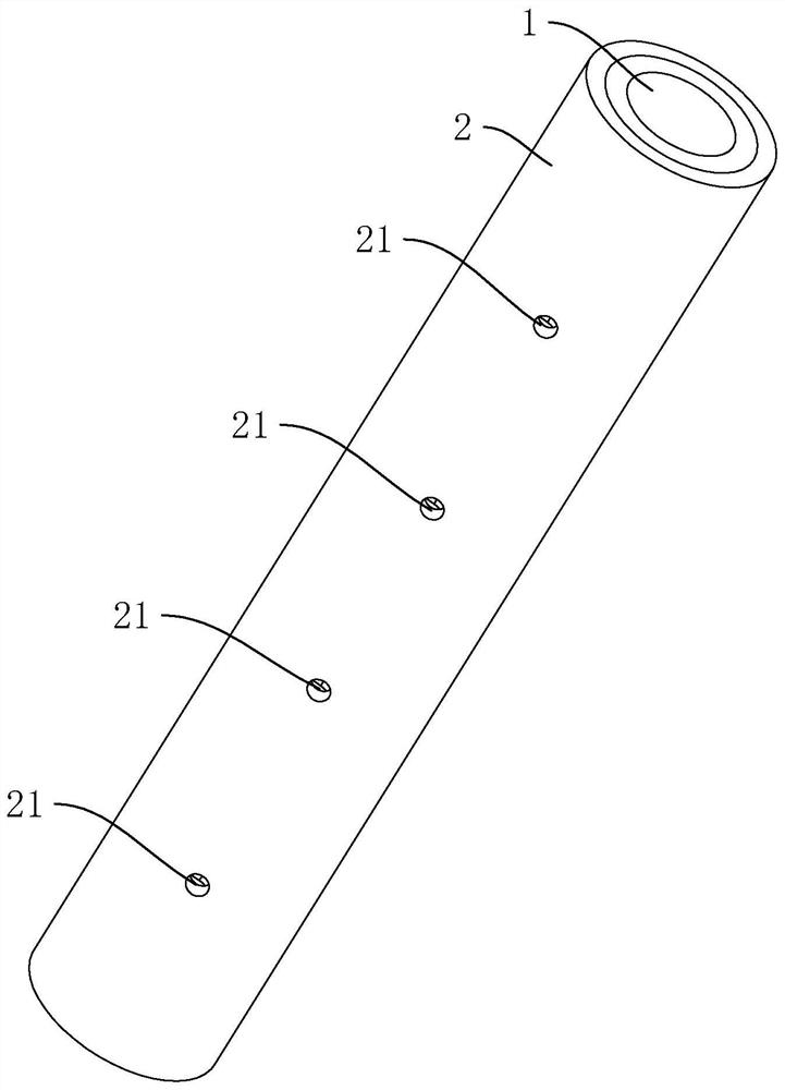
[0054] refer to figure 1 , the air supply system includes an inner pipe 1 and an outer pipe 2, and the outer pipe 2 is sleeved outside the inner pipe 1. Gas is passed into the inner tube 1, and the gas can flow out through the outer tube 2.
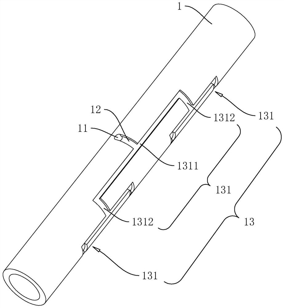
[0055] refer to figure 2 , the inner tube 1 is a round tube, one end of the inner tube 1 is closed, and the other end is open, which is used for ventilating the inner tube 1 . The outer wall of the inner tube 1 is provided with an air inlet 11, the air inlet 11 is opened in the middle of one side of the inner tube 1, the air inlet 11 runs through the side wall of the inner tube 1, and communicates with the inside of the inner tube 1.
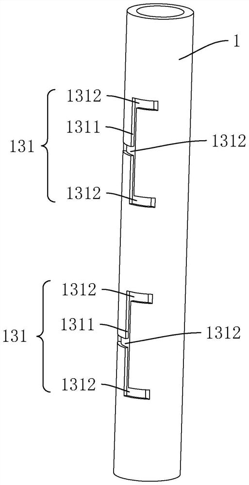
[0056] The outer wall of the inner tube 1 is provided with an air inlet groove 12, and the air inlet groove 12 is opened in the middle of the inner pipe 1. The length direction of the air inlet groove 12 is perpendicular to the length direction of the inner pipe 1, and one end of the air inlet groove 12 ...
Embodiment 2
[0068] refer to Figure 4 The difference between this embodiment and embodiment 1 is that in this embodiment, the inner pipe 1 and the outer pipe 2 are square pipes, the air inlet 11 and the air inlet groove 12 are set on one side of the inner pipe 1, and the three A groove unit 131 is provided on a side adjacent to this side of the inner pipe 1 , and an air outlet 21 is provided on a side of the outer pipe 2 . The advantage of setting the inner pipe 1 and the outer pipe 2 as square pipes is that it is convenient to process the air inlet 11 , the air inlet groove 12 and the groove unit 131 on the inner pipe 1 .
[0069] In Embodiment 1 and the present embodiment, the inner tube 1 and the outer tube 2 are respectively round tubes or square tubes. In other embodiments, the inner tube 1 and the outer tube 2 can also be tubes of other shapes, such as triangular tubes, polygonal Tubes, not limited to round tubes and square tubes.
[0070] The implementation principle of embodimen...
Embodiment 3
[0072] refer to Figure 5 The difference between this embodiment and Embodiment 1 is that there are seven trench units 131 in this embodiment. Air intake groove 12 is far away from air inlet 11 (intake groove 12 and air inlet 11 see figure 2 ) one end is connected to a groove unit 131, and the end of the groove unit 131 away from the air inlet groove 12 is connected to two groove units 131, and the ends of the two groove units 131 away from the previous groove unit 131 are respectively connected to two groove units 131.
[0073] Correspondingly, there are eight air outlets 21 in this embodiment, and the eight air outlets 21 are arranged along the length direction of the outer tube 2, and the eight air outlets 21 are connected to the four second grooves 1312 away from the air inlet groove 12 respectively. It corresponds to one end of the first groove 1311 . In this embodiment, the number of gas outlets 21 is increased, which is conducive to more dispersed and uniform flow o...
PUM
 Abstract
Description
Claims
Application Information
 - Generate Ideas
- Intellectual Property
- Life Sciences
- Materials
- Tech Scout
- Unparalleled Data Quality
- Higher Quality Content
- 60% Fewer Hallucinations
Browse by: Latest US Patents, China's latest patents, Technical Efficacy Thesaurus, Application Domain, Technology Topic, Popular Technical Reports.
© 2025 PatSnap. All rights reserved.Legal|Privacy policy|Modern Slavery Act Transparency Statement|Sitemap|About US| Contact US: help@patsnap.com