Clearing method for pulverized coal separating wheel

A cleaning method and separation wheel technology, applied in the direction of descaling devices, dryers, furnaces, etc., can solve the problems of separation wheel jamming, rotary kiln production reduction, rotary kiln material stoppage, etc., to achieve easy cleaning, ensure drying effect, Avoid the effect of dust

Active Publication Date: 2021-08-17
冀东水泥重庆合川有限责任公司
View PDF5 Cites 2 Cited by
  • Summary
  • Abstract
  • Description
  • Claims
  • Application Information

AI Technical Summary

Problems solved by technology

[0003] In the daily production process, the separation wheel is one of the key points restricting the operation of the coal mill; the raw coal moisture is very large, usually between 12-15%, especially in winter when the raw coal moisture is high and the ambient temperature is low, the raw coal is easy to be separated from the separation wheel Internal accumulation, when encountering large pieces of raw coal or other foreign objects, it is easy to jump the separation wheel, causing the mill to stop. In severe cases, the production of the rotary kiln will be reduced or even the rotary kiln will stop due to insufficient coal powder.

Method used


Image

  • Clearing method for pulverized coal separating wheel
  • Clearing method for pulverized coal separating wheel
  • Clearing method for pulverized coal separating wheel

Examples


Embodiment 1

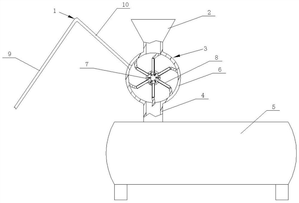
[0019] The method for cleaning the pulverized coal separation wheel is to input the hot air in the rotary kiln into the separation wheel 3 through the bent hot air duct 1, and reduce the accumulation of raw coal in the separation wheel during the rotation of the separation wheel 3.

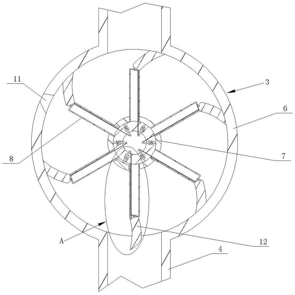
[0020] Specifically, as figure 1 As shown, the coal mill system includes a feeding hopper 2, a separating wheel 3, a grinding chute 4 and a coal mill 5, which are arranged in sequence from top to bottom, as shown in the figure. figure 2 As shown, the separation wheel 3 includes a casing 6, a rotating shaft 7 and a spacer 8 evenly distributed around the rotating shaft 7. The rotating shaft 7 and the outside of the casing 6 are bolted to the output shaft of the motor mounted on the frame by coaxial welding or by means of a method. The flange connection, that is, the rotating shaft 7 and the separating sheet 8 are rotatably arranged in the casing 6, and the casing 6 is connected with the coal mill 5...

Embodiment 2

[0024] On the basis of Embodiment 1, in addition to cleaning the raw coal inside the separation wheel 3 by hot air drying, the separation wheel 3 itself is also convenient for cleaning the pulverized coal.

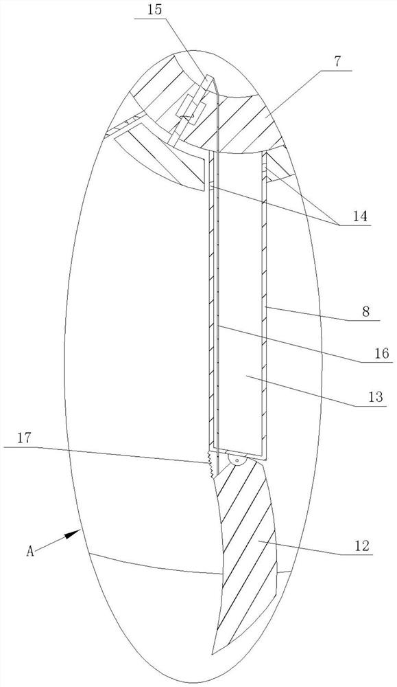
[0025] Specifically, as figure 2 As shown, the rotating shaft 7 of the separation wheel 3 is hollow, as shown in image 3 As shown, a scraper 12 is hinged on the partition 8 of the partition wheel 3 through a pin, a cavity 13 is opened in the partition 8, and a hole 14 is opened on the partition 8 that communicates with the cavity 13; adjacent partitions 8 A cleaning sheet that can block the pores 14 is slid between them. Specifically, the section of the cleaning sheet is fan-shaped, the side wall of the rotating shaft 7 has a through hole in the shape of "middle", and a sliding rod is slidably arranged in the through hole. 15. One end of the sliding rod 15 is fixedly connected with the cleaning sheet, such as welding, and a spring is sleeved on the sliding rod 15; The ...


PUM


Abstract

The invention relates to the field of separating wheel clearing, in particular to a clearing method for a pulverized coal separating wheel. The clearing method comprises the following steps: inputting hot air in a rotary kiln into a separating wheel through a bent hot air pipeline, wherein the hot air pipeline comprises an air guide tube which communicates with the rotary kiln and an air inlet tube which communicates with the separating wheel; and the connecting position between the air inlet tube and the separating wheel is a 60-90-degree interval or a 270-300-degree interval of the separating wheel. With the adoption of the technical scheme, accumulation inside the separating wheel of raw coal is favorably reduced.

Description

technical field [0001] The invention relates to the field of separation wheel cleaning, in particular to a method for cleaning a pulverized coal separation wheel. Background technique [0002] The coal mill system is an important part of cement kiln production. The existing coal mill system includes a feed hopper, a separation wheel, a grinding chute and a coal mill arranged in sequence from top to bottom, wherein the separation wheel includes a shell, a rotating shaft And the partitions evenly distributed around the rotating shaft, the rotating shaft and the partitions are arranged in the shell, and the shell is connected with the coal mill through the grinding inlet pipe, and the coal grinding system is directly related to the normal operation of the rotary kiln. [0003] In the daily production process, the separation wheel is one of the key points restricting the operation of the coal mill; the moisture content of the raw coal is very large, usually between 12-15%, espec...

Claims


Application Information

Patent Timeline
Patent Type & Authority Applications(China)
IPC IPC(8): F27D25/00F26B21/00
CPCF27D25/001F26B21/001
Inventor 谷茂董保军尚海涛朱玉田严帅
Owner 冀东水泥重庆合川有限责任公司
Why Eureka
Try Eureka