
Eureka
For R&D, Eureka makes reading and utilizing patents & technical documents easy.
Eureka AIR
Designed for self-driven R&D workflows. Generate viable solutions, solve complex R&D challenges, empower your innovation with AI.

Eureka Materials
Designed for material experts only. Revolutionize your material R&D, from search, analyze, to developing new materials.

TechResearch
Generate reliable direction feasibility study reports for your R&D in just a few steps.

TechSeek
Discover and master advanced knowledge NOW. Basics, ideas, possibilities, all at once.

TechMind
As an expert in R&D Theories, TechMind can generates customized viable solutions instantly.

TechRisk
Analyze your overall solution with one click, know your potential R&D risks in advance.

TechMonitor
Get weekly tech updates, stay abreast of the latest tech innovations and key insights.
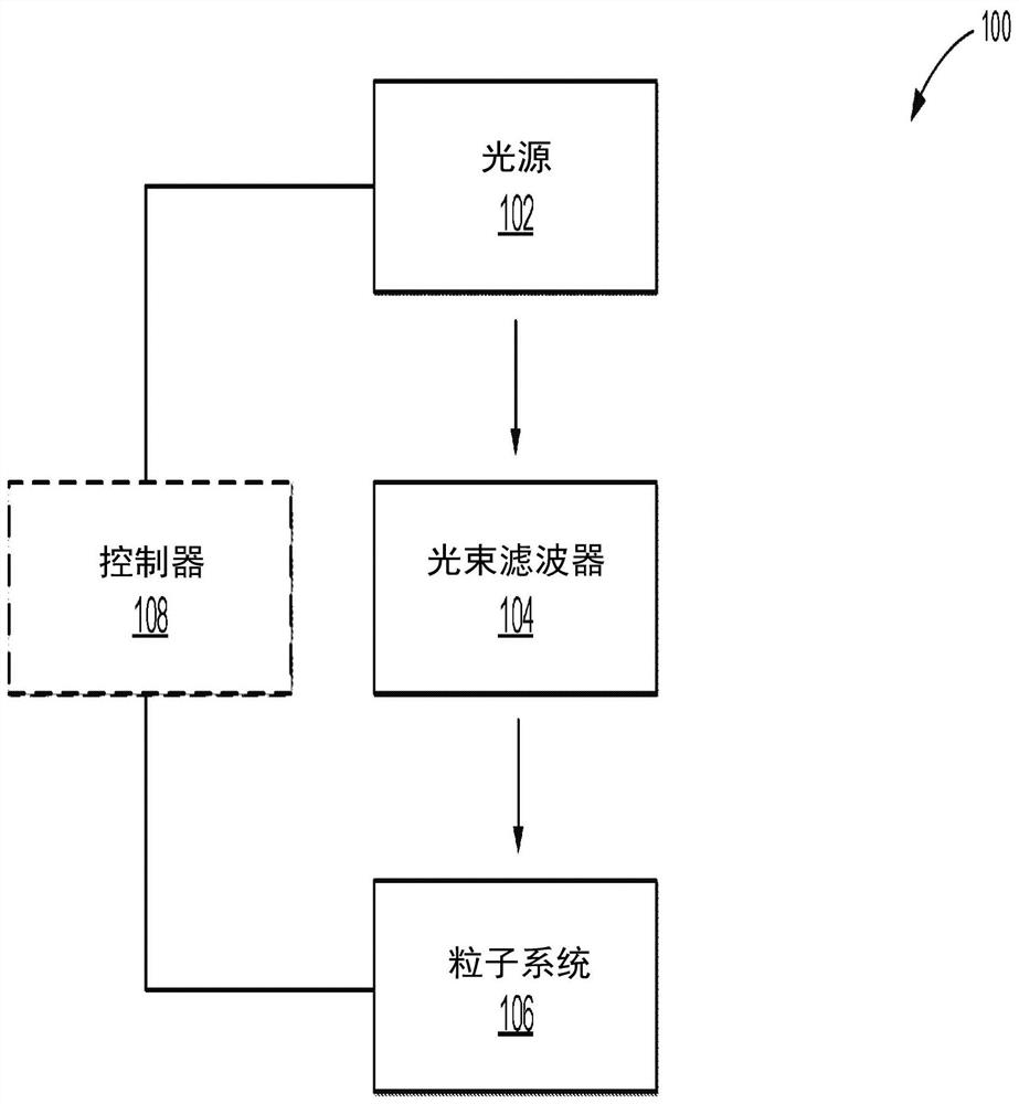
System and method for controlling particles using projected light
A particle system, light control technology, applied in the field of drawings, particle control systems, can solve problems such as increasing the complexity and cost of the system
- Summary
- Abstract
- Description
- Claims
- Application Information
AI Technical Summary
Problems solved by technology
Method used
Image

Examples
Embodiment Construction
[0026] Conventional particle trapping techniques typically rely on interference between mutually coherent beams of light. These methods have several disadvantages, including susceptibility to beam misalignment, source phase drift, and phase noise. In contrast, the inventors found that projected light fields can be used to trap particles. As detailed in US Patent 9,355,750 (which is incorporated herein by reference in its entirety), projected light fields can be used to overcome the disadvantages of conventional techniques and provide several advantages. For example, particle traps created using projected light fields are scalable, allowing deeper well depths, and do not change position or depth in response to source phase drift or noise. Additionally, each capture point requires less energy, thus allowing more points at a given energy.
[0027] While recognizing practical considerations such as ease of implementation and cost, the present disclosure introduces a novel approa...
PUM
 Abstract
Description
Claims
Application Information
 - R&D Engineer
- R&D Manager
- IP Professional
- Industry Leading Data Capabilities
- Powerful AI technology
- Patent DNA Extraction
Browse by: Latest US Patents, China's latest patents, Technical Efficacy Thesaurus, Application Domain, Technology Topic, Popular Technical Reports.
© 2024 PatSnap. All rights reserved.Legal|Privacy policy|Modern Slavery Act Transparency Statement|Sitemap|About US| Contact US: help@patsnap.com