Tailor welding equipment for three-dimensional metallic crystal lattices

A three-dimensional, lattice technology, applied in the field of metal three-dimensional lattice tailor welding equipment

Pending Publication Date: 2021-08-20
上海丹迪电力技术有限公司
View PDF0 Cites 0 Cited by
  • Summary
  • Abstract
  • Description
  • Claims
  • Application Information

AI Technical Summary

Problems solved by technology

[0004] The purpose of the invention is to solve a large number

Method used


Image

  • Tailor welding equipment for three-dimensional metallic crystal lattices
  • Tailor welding equipment for three-dimensional metallic crystal lattices
  • Tailor welding equipment for three-dimensional metallic crystal lattices

Examples


Embodiment Construction

[0033] The technical solutions are further described below with reference to the accompanying drawings and specific embodiments to help understand the content of the present invention.

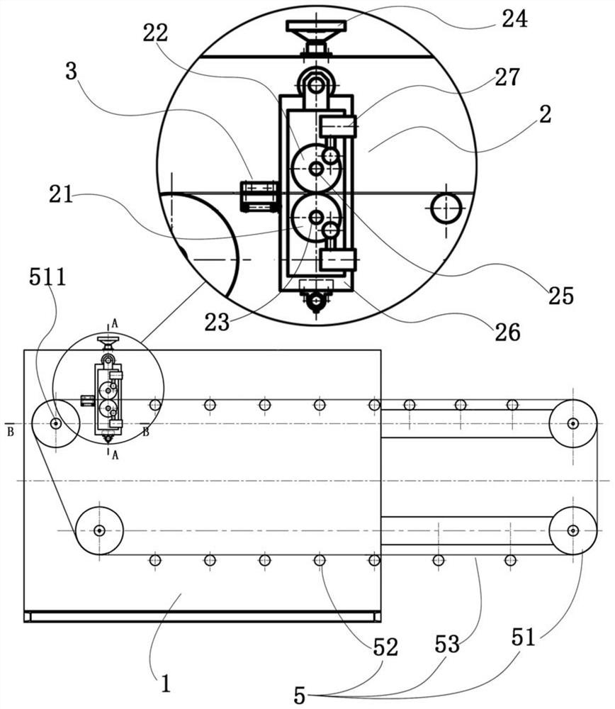
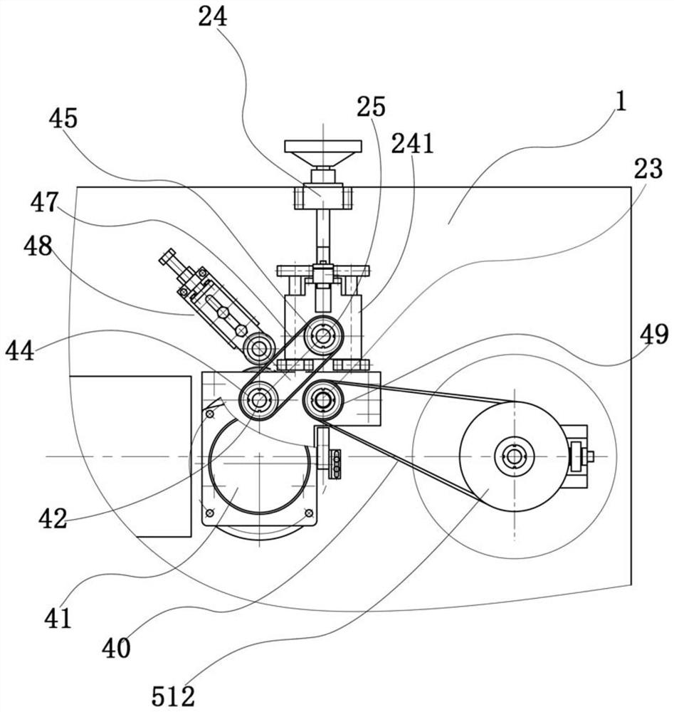
[0034] like figure 1 As shown, the present invention proposes a metal three-dimensional lattice tailor-welding equipment for continuously positioning and welding metal corrugated strips to form a metal three-dimensional lattice, which includes a frame 1 for fixing other components, a welding device 2, a feeding material guide 3 and drive unit 4 (see image 3 ).

[0035] The welding device 2 , the feeding guide rail 3 and the driving device 4 are all fixed to the frame 1 .

[0036] The metal three-dimensional lattice tailor-welding equipment also includes a guide wheel group 5 for feeding.

[0037] The guide roller group 5 includes a plurality of idler guide rollers 52 in a horizontal position and corner rollers 51 at four corners. The metal corrugated belt is annularly overlapped and conti...


PUM


Abstract

Tailor welding equipment for three-dimensional metallic crystal lattices is used for continuously positioning, welding and combining metal wave-shaped belts to form three-dimensional metallic crystal lattices and comprises a rack used for fixing other assemblies, a welding device, a feeding guide rail and a driving device. The welding device, the feeding guide rail and the driving device are all fixed to the rack. The welding device comprises a positioning gear set and a welder, and the positioning gear set is composed of a first positioning gear and a second positioning gear which operate synchronously. The tailor welding equipment further comprises a guide wheel set used for circulating feeding, the guide wheel set comprises a plurality of carrier roller guide wheels at the horizontal position and corner rolling wheels at the four corners, the carrier roller guide wheels and the corner rolling wheels jointly form an annular path for circulating feeding, and annular feeding of annular lap joint and continuous layer-by-layer welding of the metal wave-shaped belts can be achieved. The tailor welding equipment has the advantages of accurate positioning, continuous welding and high production efficiency.

Description

technical field [0001] The invention belongs to the field of mechanical manufacturing equipment, in particular to a metal three-dimensional lattice tailor-welding equipment used for the production of sealed metal three-dimensional lattice tailor-welding. Background technique [0002] In the field of high-speed turbine mechanical seals, comb labyrinth seals are widely used because of their simple structure and reliable operation. However, when the designers reduced the gap between the comb tooth tip and the shaft in order to improve the sealing effect, they found that the smaller the gap, the greater the vibration of the shaft caused by the vibration. If the vibration is too large, the sealing gap will be damaged and enlarged. When a certain value is reached, the excitation of the rotating shaft will disappear, and the excitation of the rotating shaft and the sealing gap will form a subtle mutual restraint relationship. Through experiments and studies, researchers believe th...

Claims


Application Information

Patent Timeline
IPC IPC(8): B23K37/04B23K37/047B23K37/00
CPCB23K37/00B23K37/04B23K37/047
Inventor 张永孙国胜
Owner 上海丹迪电力技术有限公司
Why Eureka
Try Eureka