Constant-temperature mold with multi-limiting function for switch injection molding

A multiple, switch technology, applied in the field of injection molds, can solve the problems of multiple limits of the inner mold, difficulty in opening the upper and lower molds, and displacement of the inner mold, so as to improve the mold opening rate and effect, improve the injection quality, and improve the stability. Effect

Pending Publication Date: 2021-08-20
杭州程意电器有限公司
View PDF9 Cites 1 Cited by
  • Summary
  • Abstract
  • Description
  • Claims
  • Application Information

AI Technical Summary

Problems solved by technology

[0004] The purpose of the present invention is: in order to solve the problem that the traditional injection mold is not equipped with a quick mold opening component outside, because the injection mold undergoes a temperature difference change, the upper and lower molds will be difficult to open, and it is necessary to manually use external tools to open the mold, and the traditional injection molding The mold is not equipped with any multiple limiting structures inside, and it is impossible to effectively and quickly perform multiple limiting on the internal inner mold. When pouring, the inner mold is prone to displacement and causes the failure of pouring. The proposed method has multiple Switching of limit function Constant temperature mold for plastic injection

Method used


Image

  • Constant-temperature mold with multi-limiting function for switch injection molding
  • Constant-temperature mold with multi-limiting function for switch injection molding
  • Constant-temperature mold with multi-limiting function for switch injection molding

Examples


Embodiment Construction

[0041] The following will clearly and completely describe the technical solutions in the embodiments of the present invention with reference to the accompanying drawings in the embodiments of the present invention. Obviously, the described embodiments are only some, not all, embodiments of the present invention. Based on the embodiments of the present invention, all other embodiments obtained by persons of ordinary skill in the art without creative efforts fall within the protection scope of the present invention.

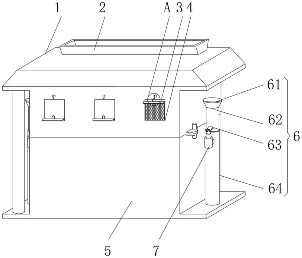
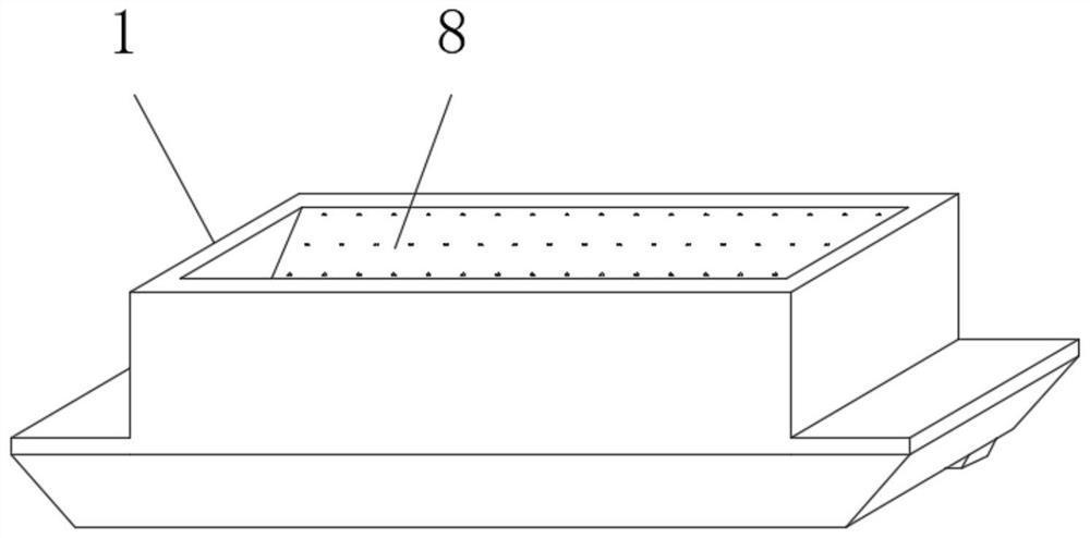
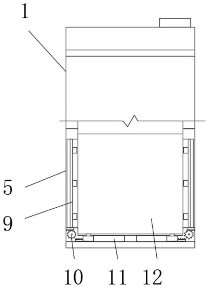
[0042] see Figure 1-9 , this embodiment discloses a constant temperature mold for switch molding with multiple limiting functions, including a first combined mold 1, a second combined mold 5, a mold opening component 6, a positioning component 7, a multiple limiting component 9, a trigger Assemblies 11 and baffles 17, the second combined mold 5 is installed under the first combined mold 1, and the mold opening assembly 6 is fixedly installed on the bottom of the s...


PUM


Abstract

The invention discloses a constant-temperature mold with a multi-limiting function for switch injection molding, and belongs to the technical field of injection molds. The constant-temperature mold comprises a first combined mold, a second combined mold, a mold opening assembly, a positioning assembly, a multi-limiting assembly, a trigger assembly and a separation blade, wherein the second combined mold is installed below the first combined mold, the mold opening assembly is fixedly installed on a bottom plate installed at the bottom of the second combined mold, and limiting pieces are fixedly installed on the outer wall of one side of the first combined mold and the outer wall of one side of the second combined mold. According to the mold, the trigger assembly and the multi-limiting assembly are installed inside, so that when an inner mold is installed at ordinary times, only the inner mold needs to be directly placed in the second combined mold, through the linkage structure design, the design is ingenious, and when the inner mold is placed and mounted, the inner mold is subjected to a rapid and synchronous multi-limiting effect, so that the stability of the inner mold in the injection molding process can be greatly improved, and the injection molding quality is effectively improved.

Description

technical field [0001] The invention belongs to the technical field of injection molds, and in particular relates to a constant temperature mold for open and close injection molding with multiple limiting functions. Background technique [0002] Injection molding is a method of producing shapes for industrial products. Products usually use rubber injection molding and plastic injection molding. Injection molding can also be divided into injection molding molding method and die-casting method. At a certain temperature, the completely molten plastic material is stirred by a screw, injected into the mold cavity with high pressure, and cooled and solidified to obtain a molded product. This method is suitable for mass production of parts with complex shapes. It is one of the important processing methods. In the injection molding process, an injection mold is required. The mold is one of the most basic structures. The mold is a tool used to make shaped objects. This tool is comp...

Claims


Application Information

Patent Timeline
Patent Type & Authority Applications(China)
IPC IPC(8): B29C45/26B29C45/27B29C45/17B29C45/73B29C45/66B29C39/26B29C39/22B29C39/38
CPCB29C45/26B29C45/2708B29C45/1742B29C45/73B29C45/66B29C39/26B29C39/22B29C39/38
Inventor 章德忠章洲彪
Owner 杭州程意电器有限公司
Why Eureka
Try Eureka