Bypass ratio ultra-wide adjustable turbofan engine structure based on variable booster stage

A turbofan engine, bypass ratio technology, applied in the direction of machines/engines, mechanical equipment, gas turbine devices, etc., can solve the problems of small size, supercharged boundary layer separation, performance attenuation, etc.

Active Publication Date: 2021-08-20
INST OF ENGINEERING THERMOPHYSICS - CHINESE ACAD OF SCI
View PDF6 Cites 7 Cited by
  • Summary
  • Abstract
  • Description
  • Claims
  • Application Information

AI Technical Summary

Problems solved by technology

[0007] In view of the coaxial and coaxial rotation speed of the supercharging stage and the fan in the existing twin-shaft turbofan engine, as the cruising altitude of the platform is getting higher and higher, the characteristic Reynolds number of the supercharging stage is constantly increasing due to the low characteristic speed and small size of the supercharging stage. reduce, causing the supercharged stage boundary layer to separate, resulting in the defects and deficiencies of rapid attenuation of performance, the present invention proposes a super-wide adjustable bypass ratio turbofan engine structure based on variable supercharged stages, and specifically relates to an application The aerodynamic layout structure of the gear-driven supercharger stage in a twin-shaft turbofan engine, and the reduction ratio is variable

Method used


Image

  • Bypass ratio ultra-wide adjustable turbofan engine structure based on variable booster stage
  • Bypass ratio ultra-wide adjustable turbofan engine structure based on variable booster stage
  • Bypass ratio ultra-wide adjustable turbofan engine structure based on variable booster stage

Examples


Embodiment Construction

[0023] In order to make the objectives, technical solutions and advantages of the present invention clearer, the technical solutions in the embodiments of the present invention will be described in more detail below in conjunction with the drawings in the embodiments of the present invention. In the drawings, the same or similar reference numerals denote the same or similar elements or elements having the same or similar functions throughout. The described embodiments are some, but not all, embodiments of the present invention, and are intended to explain the present invention, but should not be construed as limiting the present invention. Based on the embodiments of the present invention, all other embodiments obtained by persons of ordinary skill in the art without creative efforts fall within the protection scope of the present invention.

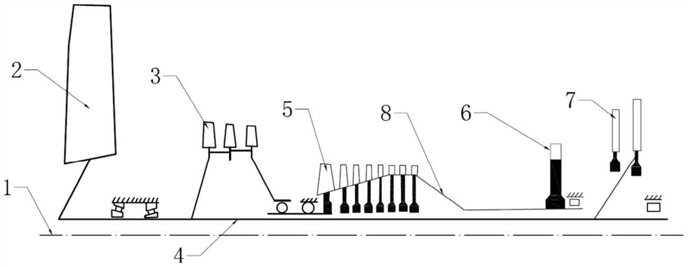
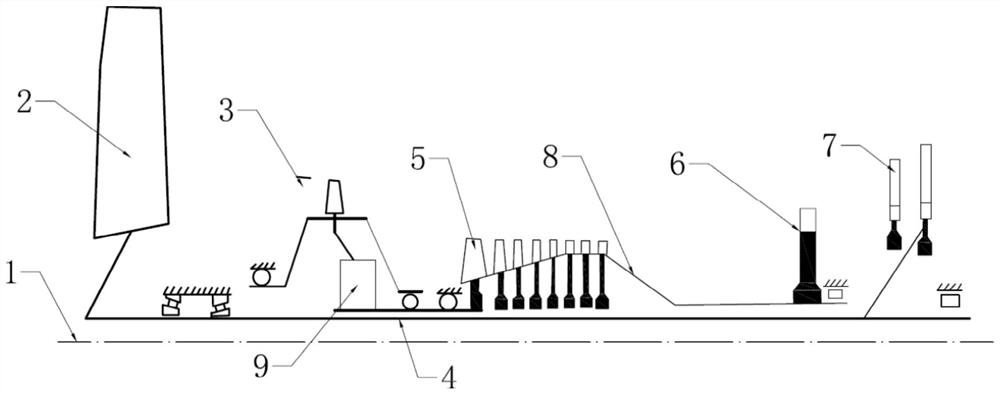
[0024] Such as figure 2 As shown, the structure of the ultra-wide adjustable turbofan engine based on the variable supercharging stag...


PUM


Abstract

The invention provides a bypass ratio ultra-wide adjustable double-shaft turbofan engine structure based on a variable booster stage. The defects and shortage that the booster stage and a fan in an existing double-shaft turbofan engine are coaxial and have the same rotating speed, as the cruising height of a platform is higher and higher, the characteristic Reynolds number of the booster stage is continuously reduced due to the fact that the characteristic speed of the booster stage is low and the size of the booster stage is small, thus a boundary layer of the booster stage is separated, and the performance is sharply decayed are overcome; the booster stage is in driving connection with a high-pressure shaft through a variable reduction ratio gearbox, when an engine cruises at a low speed, the variable reduction ratio gearbox is set to be in a high speed reduction ratio, so that the rotating speed of the booster stage is relatively low, the total temperature and the total pressure of inlet airflow of a high-pressure compressor are relatively low, and the bypass ratio of the engine is relatively large; and when the engine cruises at a high speed, the variable reduction ratio gearbox is set to be at a low reduction ratio, so that the rotating speed of the booster stage is relatively high, the mass flow sucked by the high-pressure compressor is large, and the bypass ratio of the engine is relatively small.

Description

technical field [0001] The invention belongs to the field of aviation turbofan engines, and relates to a super-wide adjustable bypass ratio turbofan engine structure based on a variable supercharging stage, in particular to an aerodynamic mechanism applied to a gear-driven supercharging stage in a twin-shaft turbofan engine. Layout structure form, and the reduction ratio is variable. Background technique [0002] Medium-bypass ratio turbofan engines are used for high-altitude and long-endurance UAVs, and multi-stage low-pressure compressors (supercharger stages) are often installed in the internal flow channel behind the fan. Since the booster stage and the fan are coaxial and rotate at the same speed, and the radial dimension of the blade tip of the booster stage is much smaller than that of the fan blade tip, the tangential speed of the blade tip of the booster stage is low, and the processing capacity is insufficient, so multi-stage is often used. To achieve the overall ...

Claims


Application Information

Patent Timeline
Patent Type & Authority Applications(China)
IPC IPC(8): F02C3/107F02C7/36F02C9/16F02K3/06F02K3/075F02K3/077
CPCF02C3/107F02C7/36F02C9/16F02K3/06F02K3/075F02K3/077
Inventor 赵胜丰卢新根徐纲朱俊强
Owner INST OF ENGINEERING THERMOPHYSICS - CHINESE ACAD OF SCI
Why Eureka
Try Eureka