

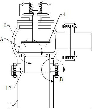
A diaphragm type mud discharge valve
A mud discharge valve and diaphragm type technology, which is applied in the field of diaphragm type mud discharge valve, can solve the problems of unfriendly overall structure of the valve body, increased maintenance difficulty, and changes in installation accuracy, and achieves little fluctuation in cost and preparation process , Facilitate the replacement and maintenance work, the effect of improving the sealing quality
- Summary
- Abstract
- Description
- Claims
- Application Information
AI Technical Summary
Problems solved by technology
Method used
Image

Examples
Embodiment Construction
[0034] The technical solutions of the present invention will be further described below in conjunction with the accompanying drawings and through specific implementation methods.
[0035] Wherein, the accompanying drawings are only for illustrative purposes, showing only schematic diagrams, rather than physical drawings, and should not be construed as limitations on this patent; in order to better illustrate the embodiments of the present invention, some parts of the accompanying drawings will be omitted, Enlargement or reduction does not represent the size of the actual product; for those skilled in the art, it is understandable that certain known structures and their descriptions in the drawings may be omitted.
[0036] In the drawings of the embodiments of the present invention, the same or similar symbols correspond to the same or similar components; , "inner", "outer" and other indicated orientations or positional relationships are based on the orientations or positional ...
PUM
 Abstract
Description
Claims
Application Information