A ferrite phase shifter magnetic core temperature detection device and detection method
A temperature detection device, ferrite technology, applied in the direction of measuring devices, thermometers, electrical devices, etc., can solve the problems of serious time delay, increase circuit complexity, reduce product performance indicators, etc., to achieve simple excitation circuit, accurate temperature The effect of simplifying collection and product structure
- Summary
- Abstract
- Description
- Claims
- Application Information
AI Technical Summary
Problems solved by technology
Method used
Image
Examples
Embodiment 1
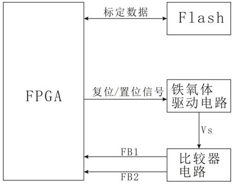
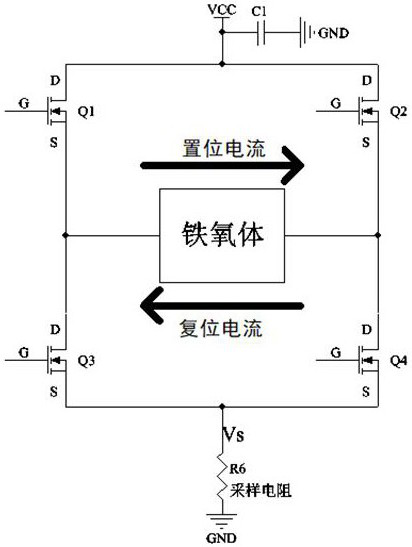
[0042] Embodiment 1: see Figure 1-Figure 4 , a ferrite phase shifter magnetic core temperature detection device, including a ferrite with an excitation coil, a ferrite drive circuit, and also includes a comparator circuit and a controller;
[0043] The ferrite drive circuit is used to change the direction of the excitation current in the ferrite, and sample the excitation current and output the sampling voltage Vs; the excitation current includes a set current and a reset current, and the current directions of the two are opposite;
[0044] The sampling voltage Vs increases with the increase of the excitation current, and when the ferrite is excited to the maximum residual magnetic flux, the sampling voltage reaches the maximum value Vsmax;
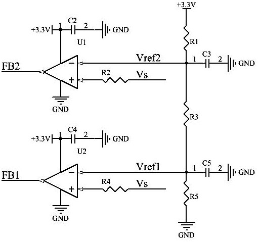
[0045] The comparator circuit includes an input terminal, a first output terminal FB1 and a second output terminal FB2, and the input terminal is connected to the sampling voltage Vs, the first reference voltage Vref1 and the second refe...
Embodiment 2
[0067] Embodiment 2: on the basis of embodiment 1, we give a kind of concrete ferrite phase shifter magnetic core temperature detection method, comprise the following steps:
[0068] (1) Construct a temperature detection device. The structure of the device is the same as in Embodiment 1, except that in the ferrite phase shifter, a ferrite material with a brand name of X8HA11 is used to make the phase shifter ferrite core. When setting the first reference voltage Vref1 and the second reference voltage Vref2, refer to image 3 , in fact, two fixed current values are set by setting two voltage values Vref1 and Vref2. If Vref1 at U1 is fixed, the current value at Vref1 must be fixed. If Vref2 at U2 is fixed, the current value at Vref2 must also be fixed.
[0069] In this embodiment, the fixed current value at Vref1 is set to 2A, that is, when the excitation current is greater than or equal to 2A, FB1 outputs a high level, and the fixed current value at Vref2 is set to 4A, th...
PUM
 Abstract
Description
Claims
Application Information
 - R&D
- Intellectual Property
- Life Sciences
- Materials
- Tech Scout
- Unparalleled Data Quality
- Higher Quality Content
- 60% Fewer Hallucinations
Browse by: Latest US Patents, China's latest patents, Technical Efficacy Thesaurus, Application Domain, Technology Topic, Popular Technical Reports.
© 2025 PatSnap. All rights reserved.Legal|Privacy policy|Modern Slavery Act Transparency Statement|Sitemap|About US| Contact US: help@patsnap.com


