
A quick-lock socket and plug

A quick-lock type, socket technology, which is applied to the base/shell, coupling device, two-part connection device, etc., can solve the problems of unsuitable for quick plugging, unsuitable for high temperature environment, and the structure is not simple enough. Less space and easy operation

Active Publication Date: 2022-05-20
CHINA AVIATION OPTICAL-ELECTRICAL TECH CO LTD
View PDF8 Cites 0 Cited by
  • Summary
  • Abstract
  • Description
  • Claims
  • Application Information

AI Technical Summary

Problems solved by technology

Both existing plugs and sockets require locking components, requiring many parts
There are also some plugs and sockets that are locked by threaded locking. After this method is inserted in place, anti-loosening measures need to be taken. At present, the commonly used anti-loosening structures include spring washer type, fuse binding type, etc. The required parts More parts, more steps
Some existing locking methods need to use elastic parts such as circlips and elastic cylindrical pins. The performance of these elastic parts may deteriorate at high temperatures and are not suitable for high temperature environments
There are also some locking components that use the VGA plug similar to the cable, the structure is not simple enough, the operation process is cumbersome, and it is not suitable for quick plugging and unplugging

Method used


Image

  • A quick-lock socket and plug
  • A quick-lock socket and plug
  • A quick-lock socket and plug

Examples


Embodiment Construction

[0030] In order to further illustrate the technical means and technical effects adopted by the present invention, the present invention will be described in detail below in conjunction with the accompanying drawings and specific embodiments.

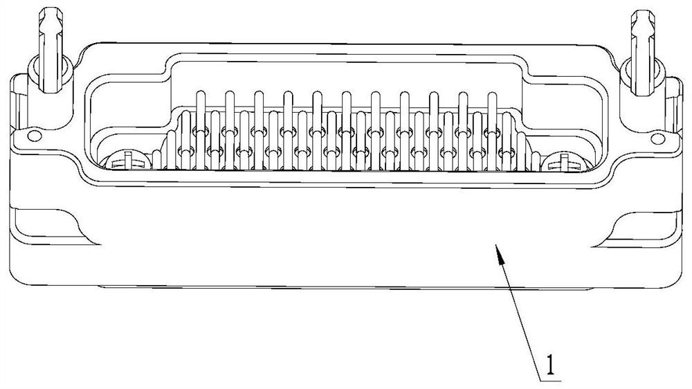
[0031] Such as Figure 3-Figure 4 As shown, the socket of the present invention includes a socket housing 1, a socket insulator 2 is assembled in the socket housing, and a pin contact 3 (also a socket contact) is fixed in the socket insulator. Both ends of the socket housing are provided with a first mounting hole 4 and a second mounting hole 5, the first mounting hole communicates with the second mounting hole, the longitudinal section of the first mounting hole is T-shaped, and the spring 6 is installed on the second mounting hole. a mounting hole. The socket housing is also provided with a locking lever, the base 7 of which is installed in the first mounting hole and is limited by the spring and the top step 22 of the first mounting ...


PUM


Abstract

The invention relates to a quick-lock socket and a plug. The socket includes a socket housing. Both ends of the socket housing are provided with a first mounting hole and a second mounting hole. A spring is installed in the first mounting hole. The base of the locking rod is installed in the first mounting hole and is limited by the spring and the top step of the first mounting hole. The upper end of the locking rod is provided with lugs. Rotation; the plug includes a plug housing, and both ends of the plug housing are provided with locks, the width of the narrowest part of the lock center through hole in the short axis direction is greater than the thickness of the lug, and the width of the widest part of the lock center through hole in the short axis direction The width is smaller than the width of the hanging lug, and the upper end surface of the lock is also provided with a stop step. In the present invention, a rotatable locking lever is provided on the socket, and a locking hole matched with the lug of the locking lever is provided on the plug, and fast locking and unlocking can be realized by rotating the locking lever. Small footprint, solid and reliable.

Description

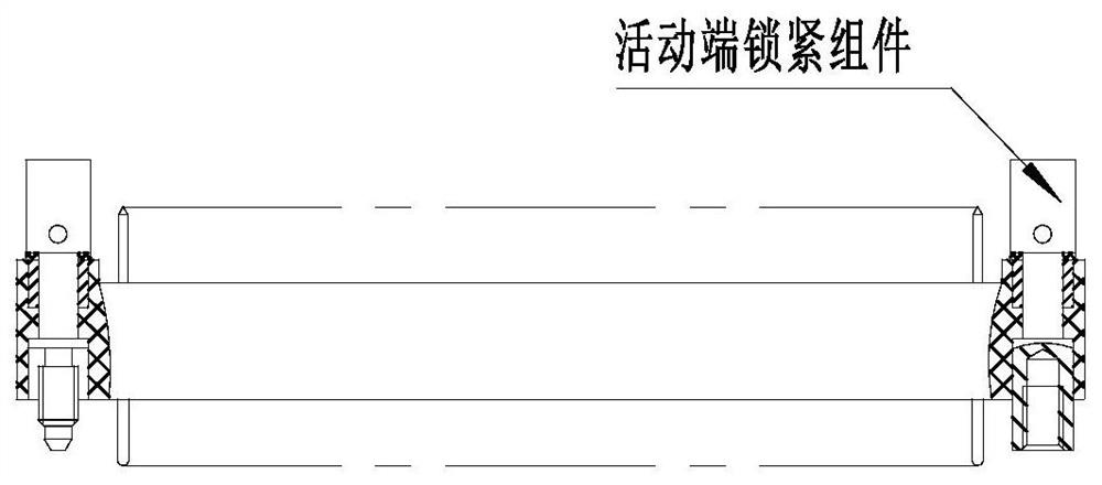
technical field [0001] The invention relates to the technical field of connectors, in particular to a quick-lock socket and plug. Background technique [0002] In connectors, plugs and sockets generally need to be locked in order to achieve a reliable electrical connection. The socket is generally fixedly installed on a certain structural member, such as figure 1 and figure 2 In the embodiment shown, the socket has a fixed-end locking component, and the plug has a movable-end locking component. After the plug and the socket are mated, the locking function is realized by operating the movable-end locking component on the plug. The existing plugs and sockets all need locking components, which require many parts. There are also some plugs and sockets that are locked by threaded locking. After this method is inserted in place, anti-loosening measures need to be taken. At present, the commonly used anti-loosening structures include spring washer type, fuse binding type, etc. ...

Claims


Application Information

Patent Timeline
Patent Type & Authority Patents(China)
IPC IPC(8): H01R24/00H01R13/639H01R13/46
CPCH01R24/005H01R13/639H01R13/46
Inventor 王贯民李跃文刘红霞
Owner CHINA AVIATION OPTICAL-ELECTRICAL TECH CO LTD
Learn More