Equipment for cooling and automatically cutting off power during continuous temperature rising of case main body

A self-power-off, main body technology, applied in the field of network technology, can solve problems such as unfavorable chassis heat dissipation, internal computer burnout, and internal circuit burnout

Pending Publication Date: 2021-08-20
杭州宗圆贸易有限公司
View PDF6 Cites 0 Cited by
  • Summary
  • Abstract
  • Description
  • Claims
  • Application Information

AI Technical Summary

Problems solved by technology

[0005] Aiming at the deficiencies of the prior art, the present invention provides a self-power-off device when the main body of the case cools down and the temperature continues to rise, which is capable of controlling the opening degree of the valve of the air duct when the internal temperature of the main body of the case rises, and increasing the amount of cooling gas per unit time. The amount of entry reduces the temperature of the chassis. When the inside of the chassis is difficult to drop, the chassis circuit is automatically disconnected to prevent the internal circuit from being burned after the temperature cannot drop. The advantage of ensuring the service life of the CPU solves the problem that the chassis is in a sealed state and is not conducive to the chassis. Heat dissipation, when the internal temperature of the chassis continues to rise and cannot effectively dissipate heat, it will cause the internal computer to burn out and cause the CPU to be damaged.

Method used


Image

  • Equipment for cooling and automatically cutting off power during continuous temperature rising of case main body
  • Equipment for cooling and automatically cutting off power during continuous temperature rising of case main body
  • Equipment for cooling and automatically cutting off power during continuous temperature rising of case main body

Examples


Embodiment Construction

[0024] The following will clearly and completely describe the technical solutions in the embodiments of the present invention with reference to the accompanying drawings in the embodiments of the present invention. Obviously, the described embodiments are only some, not all, embodiments of the present invention. Based on the embodiments of the present invention, all other embodiments obtained by persons of ordinary skill in the art without making creative efforts belong to the protection scope of the present invention.

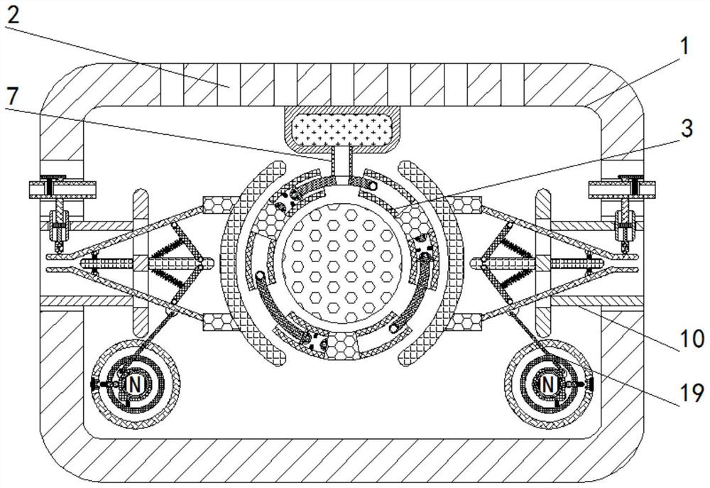
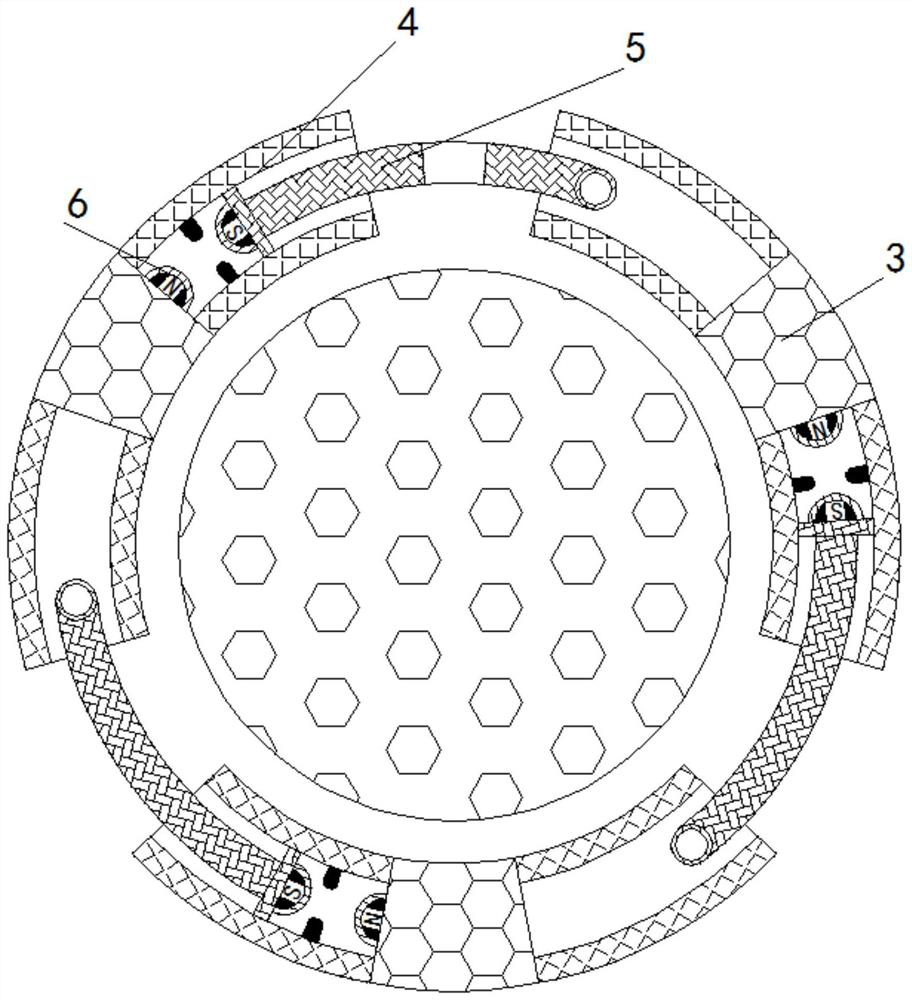
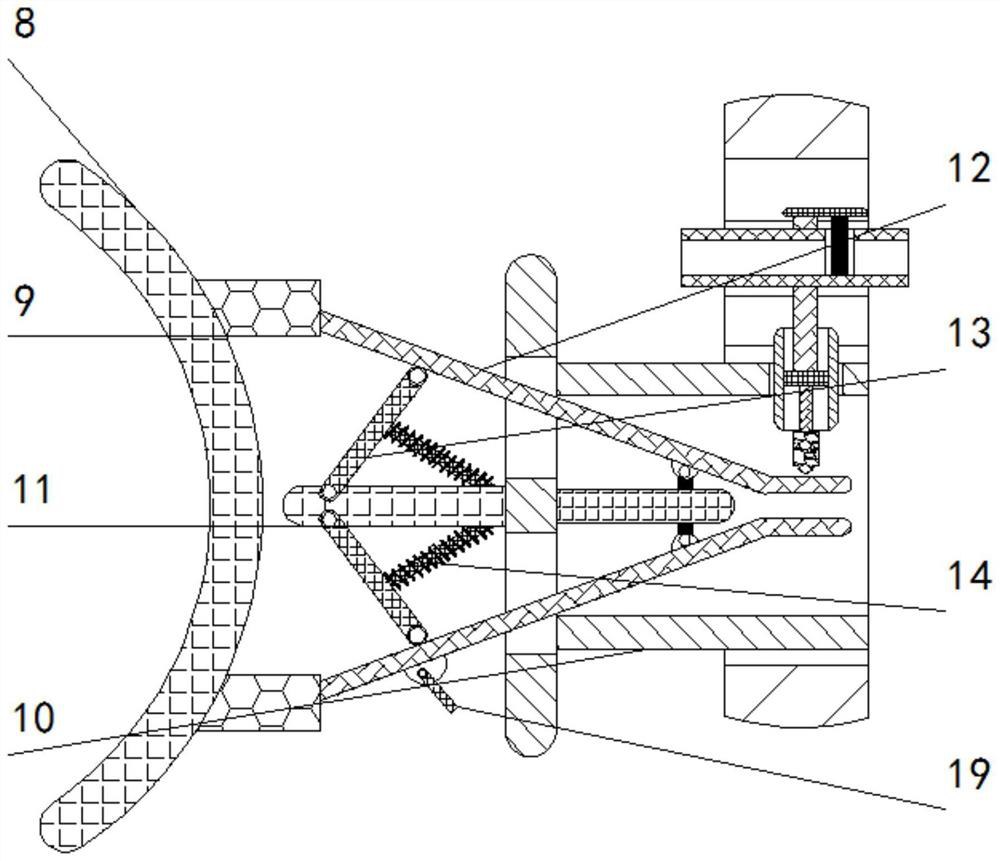
[0025] see Figure 1-5 , a self-power-off device when the main body of the chassis is cooled and the temperature continues to rise, comprising a main body of the chassis cooling device 1, a cooling hole 2 is opened on the top of the main body of the chassis cooling device 1, and a fixed disk 3 is fixedly installed inside the main body of the chassis cooling device 1 , the fixed disk 3 is a flexible disc, the inside of the fixed disk 3 is placed with a liquid t...


PUM


Abstract

The invention relates to the technical field of network science and technology, and discloses equipment for cooling and automatically cutting off power during continuous temperature rising of a case main body. The equipment comprises a case cooling equipment main body, brackets are fixedly mounted on the inner walls of the left and right sides of the case cooling equipment main body, and a rotating rod is movably mounted on the front surface of a supporting rod; and the bottom of the rotating rod is movably connected with a driving rod, the inner wall of the fixed disc is fixedly provided with a circuit break joint, the fixed disc is internally and movably provided with a rotor, and the outer wall of the rotor is slidably connected with a conducting rod. After an aqueous solution in a fixed disc is evaporated, the rotating rod at the bottom drives the driving rod to deflect, so that the rotor in the fixed disc deflects, a convex arc part on the rotor rotates to a conducting rod area, the conducting rod is pushed into a circuit break connector, and connection of a circuit in a case is stopped, and the effects of implementing automatic circuit breaking processing on the case and guaranteeing the service life of the case are achieved.

Description

technical field [0001] The invention relates to the technical field of network technology, in particular to a self-power-off device when the main body of the chassis cools down and the temperature continues to rise. Background technique [0002] As a part of computer accessories, the main function of the chassis is to place and fix various computer accessories, and play a role of support and protection. In addition, the computer case plays an important role in shielding electromagnetic radiation. The chassis generally includes a shell, a bracket, various switches on the panel, indicator lights, etc. [0003] In order to protect the internal computer accessories, the case needs to be in a sealed state to prevent dust from entering the case and causing internal circuit blockage. However, the sealed state of the chassis is not conducive to the heat dissipation of the chassis. When the internal temperature of the chassis continues to rise and cannot be effectively dissipated, ...

Claims


Application Information

Patent Timeline
Patent Type & Authority Applications(China)
IPC IPC(8): H05K7/20H01H71/00
CPCH05K7/203H01H71/00
Inventor 杨海
Owner 杭州宗圆贸易有限公司
Why Eureka
Try Eureka