Portable sampling equipment for sewage detection

A sampling device and portable technology, applied in the field of sampling devices, can solve the problems of inconvenient storage, cumbersome operation, inability to filter water sample impurities, etc., and achieve the effect of inhibiting biological changes

Pending Publication Date: 2021-12-17
蓝民江
View PDF1 Cites 0 Cited by
  • Summary
  • Abstract
  • Description
  • Claims
  • Application Information

AI Technical Summary

Problems solved by technology

[0005] In order to overcome the shortcomings of the existing sewage sampling device which is cumbersome to operate, unable to filter impurities in the water sample and inconvenient to store the water sample, the technical problem of the present invention is: to provide a sewage detection device capable of automatic clamping, automatic filtering and automatic refrigeration. with portable sampling equipment

Method used


Image

  • Portable sampling equipment for sewage detection
  • Portable sampling equipment for sewage detection
  • Portable sampling equipment for sewage detection

Examples


Embodiment 1

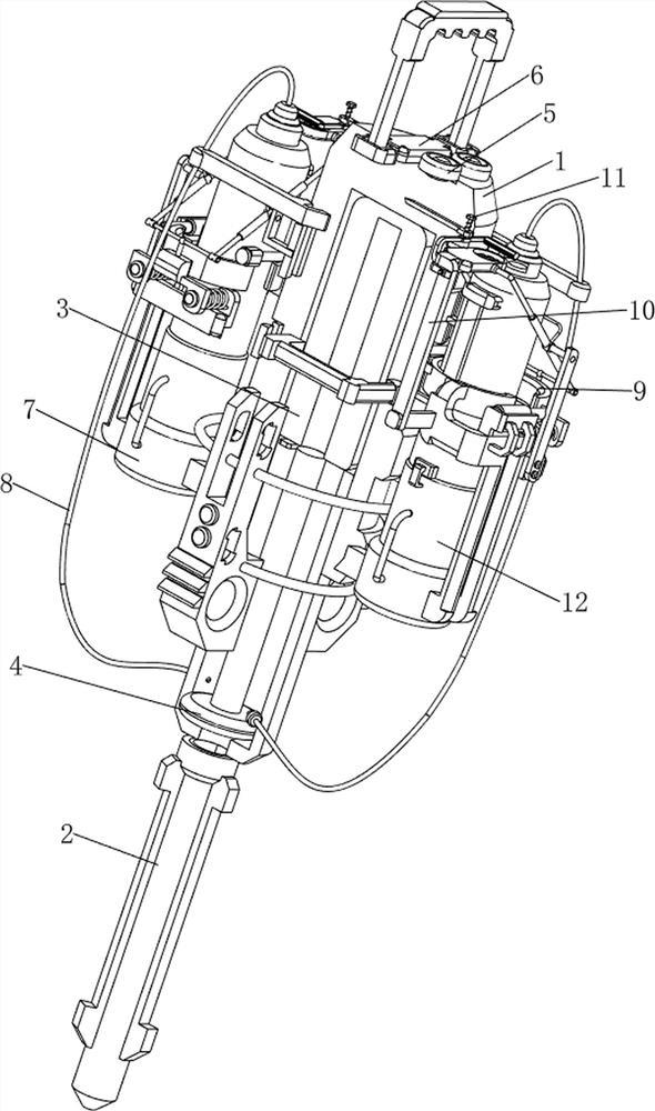
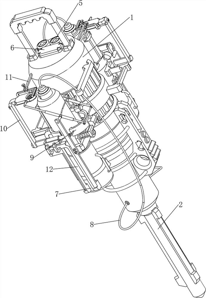
[0037] A portable sampling device for sewage testing, such as Figure 1-6 As shown, it includes a cylindrical installation tube 1, a sampling tube 2, a first electric push rod 3, a piston 4, a first contact switch 5, a placement mechanism 7 and a pumping mechanism 8, and a sampling tube is provided at the bottom of the cylindrical installation tube 1. 2. There is a first electric push rod 3 inside the cylindrical installation pipe 1, and a piston 4 is provided on the telescopic rod of the first electric push rod 3. The piston 4 is slidingly connected with the cylindrical installation pipe 1, and the top of the cylindrical installation pipe 1 A first contact switch 5 is provided at the side rear, a placement mechanism 7 is provided on the cylindrical mounting tube 1, and a pumping mechanism 8 is provided on the cylindrical mounting tube 1, and the liquid pumping mechanism 8 cooperates with the placement mechanism 7.

[0038] People put the two sampling bottles on the placement ...

Embodiment 2

[0044] On the basis of Example 1, such as figure 1 , figure 2 , image 3 , Figure 7 , Figure 8 , Figure 9 , Figure 10 , Figure 11 , Figure 12 with Figure 13 As shown, a stabilizing mechanism 9 is also included, and the stabilizing mechanism 9 includes a second pressure sensor 91, a fifth fixed mount 92, a second electric push rod 93, an arc clamp 94 and a second contact switch 95, and the top of the placement frame 71 is provided with There is a second pressure sensor 91, a fifth fixed mount 92 is arranged on the upper part of the first fixed mount 72 outside, the fifth fixed mount 92 is provided with a second electric push rod 93, and the telescopic rod of the second electric push rod 93 is connected with an arc shaped clamp 94, a second contact switch 95 is provided on the left side of the top side of the cylindrical installation tube 1 at the rear.

[0045] People put the sampling bottle between the first fixed frame 72 and the arc clamp 94, and the samplin...


PUM


Abstract

The invention relates to sampling equipment, in particular to portable sampling equipment for sewage detection. The portable sampling equipment for sewage detection can realize automatic clamping, automatic filtering and automatic refrigeration. The portable sampling equipment for sewage detection comprises a cylindrical mounting pipe, a sampling pipe, a first electric push rod, a piston, a first contact switch, a placement mechanism and a liquid pumping mechanism, wherein the sampling pipe is arranged at the bottom of the cylindrical mounting pipe; the first electric push rod is arranged on the inner side of the cylindrical mounting pipe; the piston is arranged on a telescopic rod of the first electric push rod, and the piston is in sliding connection with the cylindrical mounting pipe; the first contact switch is arranged on the cylindrical mounting pipe; the placement mechanism is arranged on the cylindrical mounting pipe; and the liquid pumping mechanism is arranged on the cylindrical mounting pipe, and the liquid pumping mechanism is matched with the placement mechanism. According to the invention, the placement mechanism and a stabilizing mechanism are arranged, and the stabilizing mechanism is matched with the placement mechanism, so that a sampling bottle is clamped, and the automatic clamping effect is achieved.

Description

technical field [0001] The invention relates to a sampling device, in particular to a portable sampling device for sewage detection. Background technique [0002] Sewage detection is a very important link in water environment monitoring. The traditional sewage detection and sampling device has a fixed style. Generally, the experimenter manually collects water samples. The collection requires the cooperation of two people. One person extracts the sampler and the other takes the sewage sample. , the operation of this type of method is too cumbersome, it is not easy to ensure the stability of water pouring, and there will be more or less sewage impurities in the collection, which will affect the test results and prolong the detection time. In addition, the existing sewage sampling device sampling The external ambient temperature is easy to change the microorganisms in the water sample. [0003] Patent application CN210375806U, the publication date is 2020.04.21, discloses a po...

Claims


Application Information

Patent Timeline
IPC IPC(8): G01N1/14G01D21/02B08B1/00B01D29/03B01D29/96B01D29/64
CPCG01N1/14G01D21/02B01D29/03B01D29/96B01D29/6407G01N2001/1418B08B1/12
Inventor 蓝民江
Owner 蓝民江
Why Eureka
Try Eureka