Eureka AIR delivers breakthrough ideas for toughest innovation challenges, trusted by R&D personnel around the world.

Soaking structure and electronic equipment

A technology of thermal structure and capillary structure, applied in electrical equipment structural parts, electrical components, cooling/ventilation/heating transformation, etc. and other problems, to reduce the difficulty of planning and design, improve the heat dissipation effect, and achieve the effect of smooth phase change

Pending Publication Date: 2021-08-20
江西新菲新材料有限公司
View PDF0 Cites 0 Cited by
  • Summary
  • Abstract
  • Description
  • Claims
  • Application Information

AI Technical Summary

Problems solved by technology

However, since the working cavity is a closed cavity, the working fluid interferes with the phase transition process of liquid and gas in the closed cavity, which affects the heat conduction rate in the closed cavity, and then affects the heat dissipation effect of the heat-spreading structure.

Method used


Image

  • Soaking structure and electronic equipment
  • Soaking structure and electronic equipment
  • Soaking structure and electronic equipment

Examples


Embodiment Construction

[0035] The following will clearly and completely describe the technical solutions in the embodiments of the present invention with reference to the accompanying drawings in the embodiments of the present invention. Obviously, the described embodiments are only some of the embodiments of the present invention, not all of them. Based on the embodiments of the present invention, all other embodiments obtained by persons of ordinary skill in the art without making creative efforts belong to the protection scope of the present invention.

[0036] In the present invention, the terms "upper", "lower", "left", "right", "front", "rear", "top", "bottom", "inner", "outer", "middle", The orientations or positional relationships indicated by "vertical", "horizontal", "horizontal", and "longitudinal" are based on the orientations or positional relationships shown in the drawings. These terms are mainly used to better describe the present invention and its embodiments, and are not intended t...


PUM


Abstract

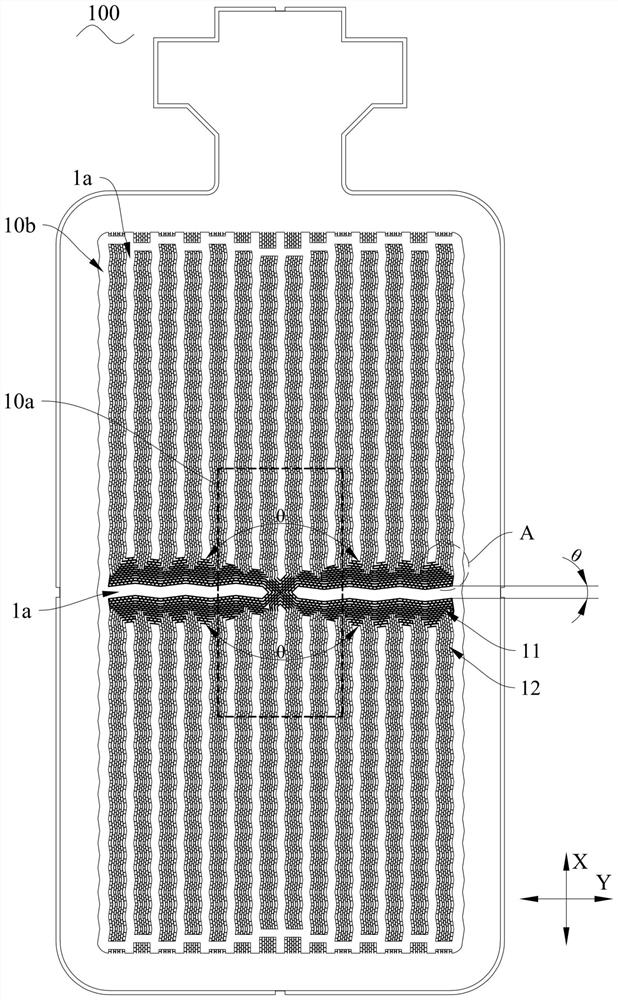
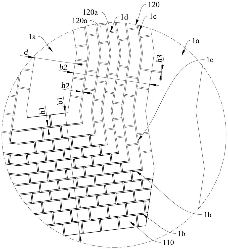
The invention discloses a soaking structure which comprises a plate body. The plate body is provided with a heating area and a condensation area located on the periphery of the heating area, the heating area is used for being connected with a heating source, the plate body is provided with a plurality of first capillary structures and a plurality of second capillary structures, and the first capillary structures are radially distributed towards the condensation area with the heating area as the center; a first liquid channel is formed in the first capillary structure, the second capillary structure extends to the condensation area from the first capillary structure in the first direction or the second direction of the plate body, a second liquid channel is formed in the second capillary structure, a gas channel is formed between every two adjacent capillary structures, and the first direction is perpendicular to the second direction; and the first capillary structures are radially distributed towards the condensation area with the heating area as the center, the liquid backflow path can be shortened, the second capillary structures extend in the first direction or the second direction, and the distribution planning and design difficulty of the second capillary structures on the plate body can be lowered. In addition, the invention also discloses electronic equipment comprising the soaking structure.

Description

technical field [0001] The invention relates to the technical field of heat dissipation structures, in particular to a heat uniform structure and electronic equipment. Background technique [0002] During the use of electronic equipment, the electronic devices in the electronic equipment will generate a lot of heat, which will lead to an increase in the ambient temperature of the electronic devices. However, the electronic devices will be in a high temperature environment for a long time, which will shorten the service life of the electronic devices. . In related technologies, in order to take into account the light and thin design of electronic equipment, VC (Vapor Chamber, vacuum chamber thermal structure heat dissipation technology) thermal structure is often used to dissipate heat from electronic devices (such as chips, batteries, etc.), the VC thermal structure mainly It includes an upper heat conduction sheet and a lower heat conduction sheet, a closed cavity is forme...

Claims


Application Information

Patent Timeline
Patent Type & Authority Applications(China)
IPC IPC(8): H05K7/20
CPCH05K7/20318H05K7/20327H05K7/20336
Inventor 王冬明程志政
Owner 江西新菲新材料有限公司
Why Eureka
Eureka Blog
Learn More