Automatic discharging ring rolling mill and using method thereof

A technology of automatic unloading and ring rolling machine, applied in forging/pressing/hammering machinery, manufacturing tools, forging/pressing/hammer devices, etc., can solve the problems of cumbersome installation, high price, hindering the operation space of the mandrel, etc. Achieve the effect of simple modification, low cost and convenient assembly line operation

Inactive Publication Date: 2021-08-24
浙江华工锻造有限公司
View PDF0 Cites 0 Cited by
  • Summary
  • Abstract
  • Description
  • Claims
  • Application Information

AI Technical Summary

Problems solved by technology

[0003] At present, due to the setting of the base, side rollers, upper hanging rollers, and front rollers, the ring rolling machine hinders the operating space near the mandrel, and the unloading of the ring rolling machine is inconvenient. For hole processing, manual unloading needs to wait for the hot forging to cool down or use other devices for unloading. The operation is cumbersome and inconvenient, and does not meet the needs of automation. There are automatic unloading equipment for CNC ring rolling machines in the prior art, but they mainly rely on mechanical arms. Or artificial intelligence operation, cumbersome installation and high price, which is not conducive to large-scale and low-cost use of factories

Method used


Image

  • Automatic discharging ring rolling mill and using method thereof
  • Automatic discharging ring rolling mill and using method thereof
  • Automatic discharging ring rolling mill and using method thereof

Examples


Embodiment Construction

[0031] The present invention will be further described below in conjunction with accompanying drawing:

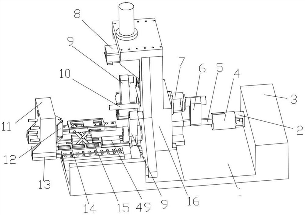
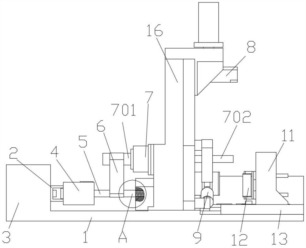
[0032] Referring to the accompanying drawings: an automatic unloading ring rolling machine in this embodiment includes a base 1, a back seat 3 fixedly connected to the rear end of the base 1 and a support plate 16 fixedly connected to the upper end of the middle part of the base 1, the left end of the back seat 3 The mounting seat 2 is fixedly connected, and the left end of the mounting seat 2 is fixedly connected with an adjustment part 4, and the left end of the adjustment part 4 is rotatably connected with a rotating shaft 5, and the outside of the rotating shaft 5 is fixedly connected with a bearing 30 at the left end and a bearing at the right end. Bearing two 34, the outer side of the first bearing 30 and the second bearing 34 is fixedly connected with a transmission part 31, the outer side of the transmission part 31 is connected with one end of the conveyor belt 6, a...


PUM


Abstract

The invention discloses an automatic discharging ring rolling mill. The automatic discharging ring rolling mill comprises a base, a rear seat fixedly connected to the rear end of the base and a supporting plate fixedly connected to the upper end of the middle of the base, a mounting seat is fixedly connected to the left end of the rear seat, an adjusting part is fixedly connected to the left end of the mounting seat, and a rotating shaft is rotationally connected to the left end of the adjusting part. A first bearing at the left end and a second bearing at the right end are fixedly connected to the outer side of the rotating shaft, a transmission part is fixedly connected to the outer side of the first bearing and the outer side of the second bearing, one end of a conveying belt is in transmission connection to the outer side of the transmission part, a double-head motor is fixedly connected to the middle end of the supporting plate, and a main grinding roller is fixedly connected to an output shaft at the left end of the double-head motor. The right end of the double-end motor is fixedly connected with a driving shaft, the driving shaft is in transmission connection with the other end of the conveying belt, the left end of the conveying rotating shaft is fixedly connected with a lead screw part, the lower end of the supporting plate is slidably connected with a boss, and a tapping hole is formed in the middle end of the boss.

Description

technical field [0001] The invention relates to the field of forging, in particular to an automatic unloading ring milling machine and a use method thereof. Background technique [0002] The ring rolling machine is also called rolling expanding machine or hole reaming machine. When processing forged flanges, the ring rolling machine is used to ream the hot forgings. According to the form of the frame and the position of the ring parts, the ring rolling machine can be divided into two types: vertical type and horizontal type. The vertical ring rolling machine is mainly composed of a frame, a rolling roller, a core roller, a guide roller and a measuring roller. Both the roller and the measuring roller are connected to the frame in rotation, and the rolling roller is connected to the frame in a sliding manner at the same time. When processing the flange, the flange blank is placed on the mandrel, and then the rolling roller is placed on the mandrel. While rotating, it slides ...

Claims


Application Information

Patent Timeline
Patent Type & Authority Applications(China)
IPC IPC(8): B21J13/14B21J13/08
CPCB21J13/08B21J13/14
Inventor 张良茅毛政彬
Owner 浙江华工锻造有限公司
Why Eureka
Try Eureka