Mold for manufacturing waterproof ring and production method of waterproof ring
A production method and technology for waterproof rings, which are applied in the production field of molds and waterproof rings, can solve the problems of residual density of waste edges, unevenness, poor waterproof effect, etc., and achieve the effect of improving waterproof effect.
- Summary
- Abstract
- Description
- Claims
- Application Information
AI Technical Summary
Problems solved by technology
Method used
Image

Examples
Embodiment Construction
[0027] The implementation of the present application will be described in detail below with reference to the accompanying drawings and examples, so as to fully understand and implement the implementation process of how the present application uses technical means to solve technical problems and achieve technical effects.
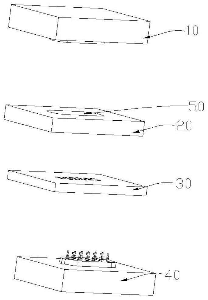
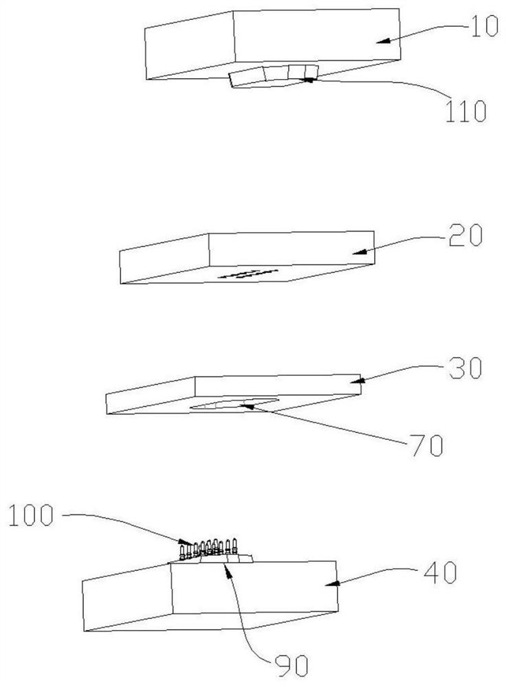
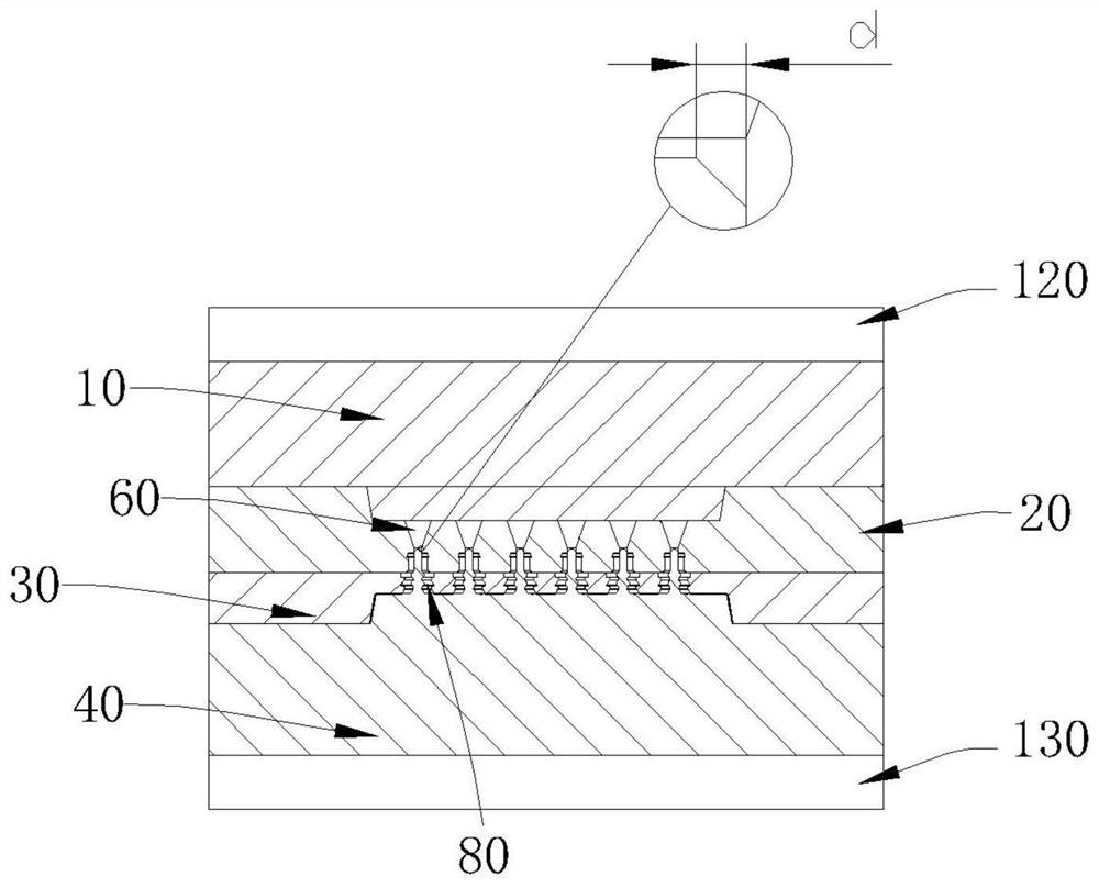
[0028] Such as Figure 1-3 As shown, the present invention adopts the following technical scheme. A mold for making a waterproof ring includes an upper template 10 and a lower template 40, and a middle upper plate 20 and a middle upper plate 20 are arranged between the upper template 10 and the lower template 40. The lower plate 30, the first side of the middle and upper plate 20 is recessed toward the side of the middle and lower plate 30 to form a first material placement cavity 50, and a material feeding hole 60 is opened in the first material setting cavity 50, and the material feeding The hole 60 is set through the first material storage chamber 50, and...
PUM
 Abstract
Description
Claims
Application Information
 - R&D
- Intellectual Property
- Life Sciences
- Materials
- Tech Scout
- Unparalleled Data Quality
- Higher Quality Content
- 60% Fewer Hallucinations
Browse by: Latest US Patents, China's latest patents, Technical Efficacy Thesaurus, Application Domain, Technology Topic, Popular Technical Reports.
© 2025 PatSnap. All rights reserved.Legal|Privacy policy|Modern Slavery Act Transparency Statement|Sitemap|About US| Contact US: help@patsnap.com