Automatic barrel rotating equipment and barrel rotating method
A barrel-turning, automatic technology, applied in the field of industrial production, can solve the problems of barrel deformation, inaccurate positioning, high structural strength requirements, etc., and achieve the effects of short manufacturing cycle, good compatibility, simple and reliable structure
- Summary
- Abstract
- Description
- Claims
- Application Information
AI Technical Summary
Problems solved by technology
Method used
Image

Examples
Embodiment 1
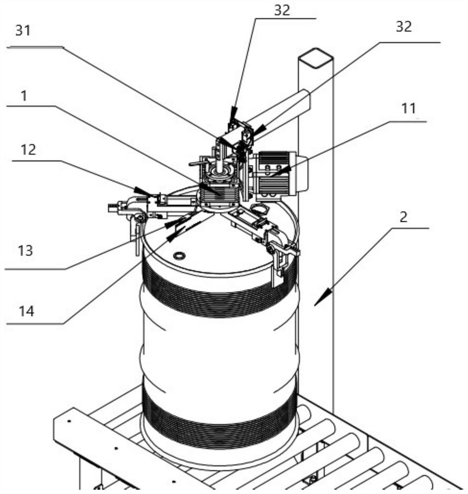
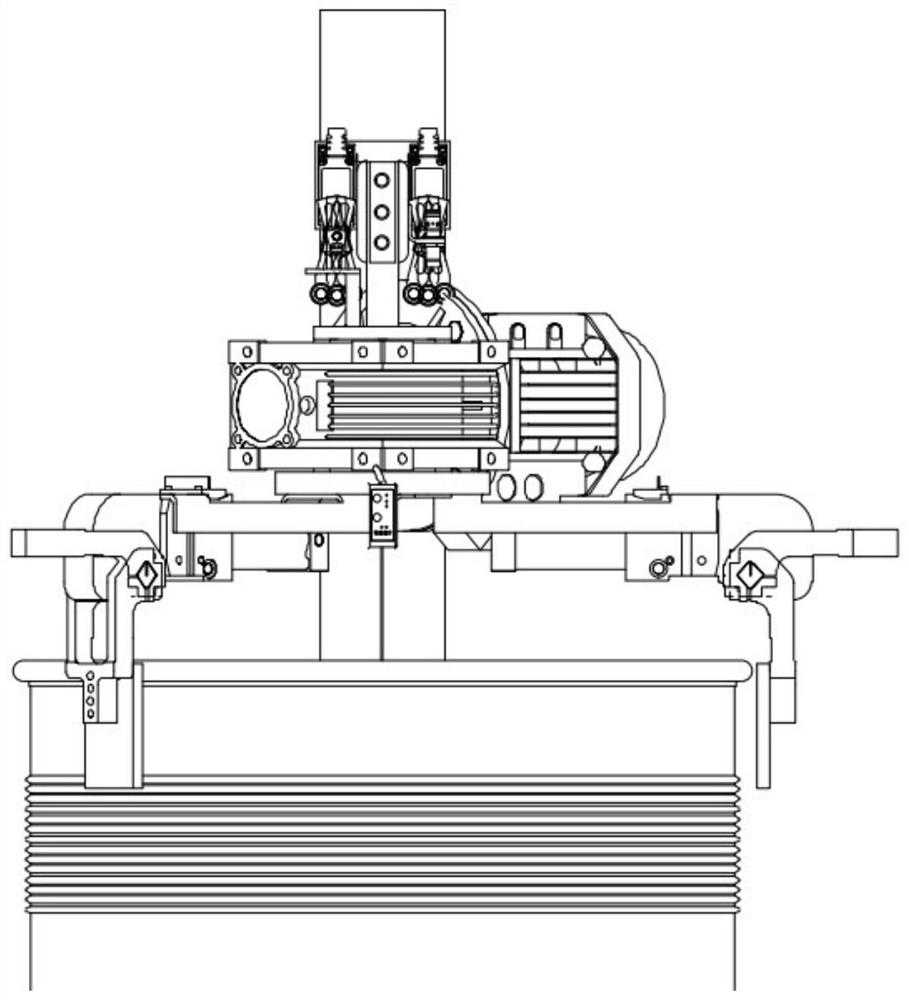
[0042] This embodiment provides a fully automatic drum rotating device, which includes a drum rotating unit 1 , a supporting unit 2 , a driving unit 11 and an identification and detection unit 13 .
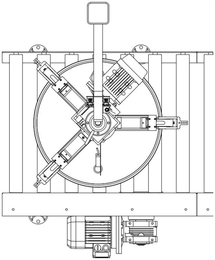
[0043] The rotary barrel unit 1 is connected to the support unit 2 in a rotating manner, and the rotary barrel unit 1 can rotate around the vertical axis of rotation, and the roller table can transport the bucket to the bottom of the rotary barrel unit 1; The rotating shaft of 1 is provided with a plurality of clamping parts 6 that extend outward in the horizontal direction and can be flipped down to be clamped on the top edge of the bucket; unit 1 to be able to detect the position of the mouth of the barrel; the drive unit is fixed on the support unit and is used to drive the rotary barrel unit 1 and the identification detection unit 13 on its upper part to rotate, and the identification detection unit 13 detects the mouth of the barrel After the position, drive the barrel unit 1...
Embodiment 2
[0054] Such as figure 1 As shown, this embodiment provides a fully automatic drum rotating device, which consists of a drum rotating unit 1, a support unit 2 and an in-position detection unit. The difference between this embodiment and the first embodiment is as follows.
[0055] The drive unit 11 is a motor and a reducer connected thereto. The motor is a three-phase asynchronous motor. The output shaft of the reducer is directly fixed to the supporting unit 2, so the driving unit 11 rotates by itself when working, driving the rotating actuator 12 on it to rotate, and completes the actions of laser ranging, finding the bucket opening and rotating the bucket . The shaft of the motor is horizontal, and the motor is installed on the side of the reducer; the highest point of the motor is lower than the lowest point of the horizontal connector of the support unit 2; the lowest point of the motor is higher than the lowest point of the rotating arm. The motor and identification d...
Embodiment 3
[0060] The embodiment of the present invention also provides a method for rotating barrels, including:
[0061] The barrel is conveyed to the bottom of the rotary barrel unit through the roller table, so that the clamping part of the rotary barrel unit can clamp the barrel;
[0062] Keep the drum unit at the initial position, and make at least two of the clamping parts on the drum unit on the same side as the conveying direction of the roller table turn down to block and position the drum , keep other clamping parts in the initial state, so that the barrel can smoothly enter directly under the barrel unit without being hindered; when the barrel unit is in the initial position, identify the position of the detection unit, which is the barrel to be rotated The target azimuth to be reached by turning the barrel at the mouth of the barrel; Figure 5 As shown, in this embodiment, three clamping parts are used, wherein one clamping part on the right side is in a horizontal state, a...
PUM
 Abstract
Description
Claims
Application Information
 - R&D
- Intellectual Property
- Life Sciences
- Materials
- Tech Scout
- Unparalleled Data Quality
- Higher Quality Content
- 60% Fewer Hallucinations
Browse by: Latest US Patents, China's latest patents, Technical Efficacy Thesaurus, Application Domain, Technology Topic, Popular Technical Reports.
© 2025 PatSnap. All rights reserved.Legal|Privacy policy|Modern Slavery Act Transparency Statement|Sitemap|About US| Contact US: help@patsnap.com