
Fixed switch cabinet

A switchgear and fixed technology, applied in the field of switchgear, can solve the problems of the normal use of the switchgear, reduce the service life of the pulley, affect the stability of the switchgear, etc., to reduce long-term contact, reduce impact, and protect electronic equipment. Effect

Inactive Publication Date: 2021-08-24
南通正耀电气科技有限公司
View PDF0 Cites 0 Cited by
  • Summary
  • Abstract
  • Description
  • Claims
  • Application Information

AI Technical Summary

Problems solved by technology

[0003] For some movable switch cabinets, the role of the pulley is very important, and the pulley is in contact with the ground for a long time, which will not only affect the stability of the switch cabinet, but also reduce the service life of the pulley and increase a certain The economic cost has affected the normal use of subsequent switchgear

Method used


Image

  • Fixed switch cabinet
  • Fixed switch cabinet

Examples


Embodiment Construction

[0016] The following will clearly and completely describe the technical solutions in the embodiments of the present invention with reference to the accompanying drawings in the embodiments of the present invention. Obviously, the described embodiments are only some, not all, embodiments of the present invention. Based on the embodiments of the present invention, all other embodiments obtained by persons of ordinary skill in the art without making creative efforts belong to the protection scope of the present invention.

[0017] In the description of the present invention, it should be noted that the terms "upper", "lower", "inner", "outer", "front end", "rear end", "both ends", "one end", "another end" The orientation or positional relationship indicated by etc. is based on the orientation or positional relationship shown in the drawings, and is only for the convenience of describing the present invention and simplifying the description, rather than indicating or implying that ...


PUM


Abstract

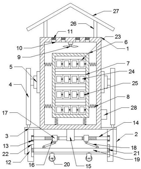
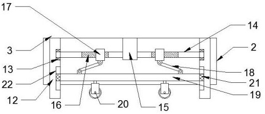
A fixed switch cabinet disclosed by the present invention comprises a switch cabinet body, a bottom box is fixedly connected to the bottom of the switch cabinet body, limiting blocks are arranged on the two sides of the top of the bottom box, supporting rods are installed above the limiting blocks, fixing blocks are fixedly connected between the inner sides of the supporting rods and the switch cabinet body, and a frame body is arranged in the switch cabinet body. Switch boxes which are uniformly distributed are fixedly connected to the frame body, damping springs are uniformly distributed between the periphery of the frame body and the inner wall of the switch cabinet, a cooling fan is fixedly installed at the position, close to the top, of the switch cabinet, air outlets which are uniformly distributed are formed in the top of the switch cabinet, and dustproof nets are installed in the air outlets. The bottom of the bottom box is connected with supporting legs, and the supporting legs extend to the top of the interior of the bottom box. Through the arrangement of the switch cabinet, the damping spring, the frame body and the switch box, the damping effect can be achieved when the switch cabinet is impacted, so that impact on electronic equipment in the switch box is reduced, and the effect of protecting the electronic equipment is achieved.

Description

technical field [0001] The invention relates to the technical field of switch cabinets, in particular to a fixed switch cabinet. Background technique [0002] The switch cabinet is a kind of electrical equipment. The outside line of the switch cabinet first enters the main control switch in the cabinet, and then enters the sub-control switch. Each branch is set according to its needs, such as instruments, automatic control, motor magnetic switches and various AC contactors. There are also switch cabinets in high-voltage room and low-voltage room, and high-voltage busbars, such as power plants, etc., and fixed switch cabinets refer to switch cabinets in which all electrical components in the cabinet are fixed installations. [0003] For some movable switch cabinets, the role of the pulley is very important, and the pulley is in contact with the ground for a long time, which will not only affect the stability of the switch cabinet, but also reduce the service life of the pulle...

Claims


Application Information

Patent Timeline
IPC IPC(8): H02B1/30H02B1/54
CPCH02B1/303H02B1/54
Inventor 周玮
Owner 南通正耀电气科技有限公司
Learn More