Oil blending device capable of reducing static accumulation

An oil and static electricity technology, which is applied in the field of oil blending devices to reduce static electricity accumulation, can solve problems such as stratification or swirl formation, single stirring effect, etc., and achieve the effect of reducing static electricity accumulation

Active Publication Date: 2021-08-27
DONGYING HUAYA GUOLIAN AVIATION FUEL CO LTD
View PDF9 Cites 3 Cited by
  • Summary
  • Abstract
  • Description
  • Claims
  • Application Information

AI Technical Summary

Problems solved by technology

[0002] Various base oils are obtained from petroleum through different refining methods. The base oil cannot meet the national and industry quality standards. Several base oils need to be mixed and stirred evenly according to a certain proportion, and additives with certain functions are added at the same time to make the oil product The quality indicators meet or exceed the standard requirements; at the same time, during the long-term storage of the blended oil products, slight stratification will occur due to the different densities of various base oils, so the oil products need to be stirred regularly, and the machinery in the tank Stirring is the most common stirring method, but the stirring blades of the existing mechanical stirring device are fixed on the stirring shaft, the stirring effect is single, and it is easy to cause the stirred oil to stratify or form a swirl, which cannot meet the actual needs, so we invented An oil blending device to reduce static electricity accumulation

Method used


Image

  • Oil blending device capable of reducing static accumulation
  • Oil blending device capable of reducing static accumulation
  • Oil blending device capable of reducing static accumulation

Examples


Embodiment Construction

[0015] In order to make the purpose, technical solutions and advantages of the embodiments of the present invention clearer, the technical solutions in the embodiments of the present invention will be clearly and completely described below in conjunction with the drawings in the embodiments of the present invention. Obviously, the described embodiments It is a part of embodiments of the present invention, but not all embodiments. Based on the embodiments of the present invention, all other embodiments obtained by persons of ordinary skill in the art without creative efforts fall within the protection scope of the present invention.

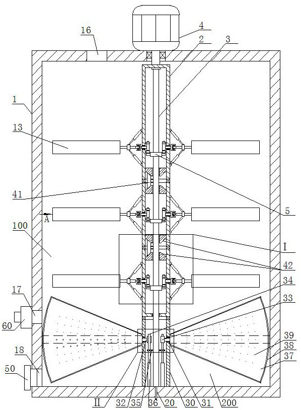
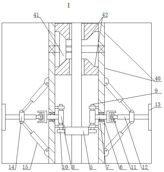
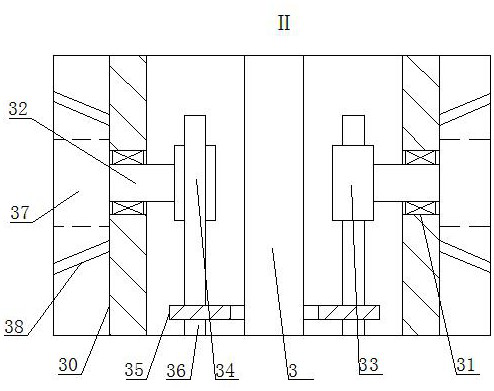
[0016] An oil blending device that reduces static electricity accumulation, such as Figure 1-5 As shown, it includes a tank body 1, a rotating tube 2 is installed in the tank body 1, a fixed shaft 3 is installed in the rotating tube 2, one end of the fixed shaft 3 is fixedly connected with the tank body 1, and the upper end of the fixed shaft 3 i...


PUM


Abstract

The invention relates to an oil blending device capable of reducing static accumulation, which belongs to the field of oil blending devices, and comprises a tank body, a rotating pipe rotatably mounted in the tank body, a fixed shaft rotatably mounted in the rotating pipe, one end of the fixed shaft fixedly connected with the tank body, and a driving motor fixedly mounted on the tank body and capable of driving the rotating pipe to rotate. A plurality of annular gears are fixedly installed on the periphery of the fixing shaft, a plurality of first through holes which are evenly distributed in the circumferential direction are formed in the periphery of the rotating pipe and correspond to the annular gears, and the inner peripheries of the first through holes are rotationally connected with the periphery of a first rotating rod through sealing bearings. The device is simple in structure and ingenious in conception, when the stirring plate rotates along with the rotating pipe to transversely stir an oil product, the stirring plate can swing up and down through resistance of the oil product to the stirring plate, so that the stirring plate vertically stirs the oil product, meanwhile, by changing the angle of the stirring plate, the stirring plate can push the oil product upwards or downwards when rotating, the vertical stirring effect is further improved, so that the oil product is fully stirred.

Description

technical field [0001] The invention belongs to the field of oil blending devices, in particular to an oil blending device that reduces static electricity accumulation. Background technique [0002] Various base oils are obtained from petroleum through different refining methods. The base oil cannot meet the national and industry quality standards. Several base oils need to be mixed and stirred evenly according to a certain proportion, and additives with certain functions are added at the same time to make the oil product The quality indicators meet or exceed the standard requirements; at the same time, during the long-term storage of the blended oil products, slight stratification will occur due to the different densities of various base oils, so the oil products need to be stirred regularly, and the machinery in the tank Stirring is the most common stirring method, but the stirring blades of the existing mechanical stirring device are fixed on the stirring shaft, the stirr...

Claims


Application Information

Patent Timeline
IPC IPC(8): B01F11/00
CPCB01F31/44
Inventor 石军王凯张健张海旭陈占先
Owner DONGYING HUAYA GUOLIAN AVIATION FUEL CO LTD
Why Eureka
Try Eureka