Building safety helmet paint spraying device
A technology for safety helmets and automatic painting, which is applied in the direction of spraying devices, liquid spraying devices, and devices for coating liquid on the surface, which can solve the problems of slow stamping speed of safety helmets
- Summary
- Abstract
- Description
- Claims
- Application Information
AI Technical Summary
Problems solved by technology
Method used
Image
Examples
Embodiment 1
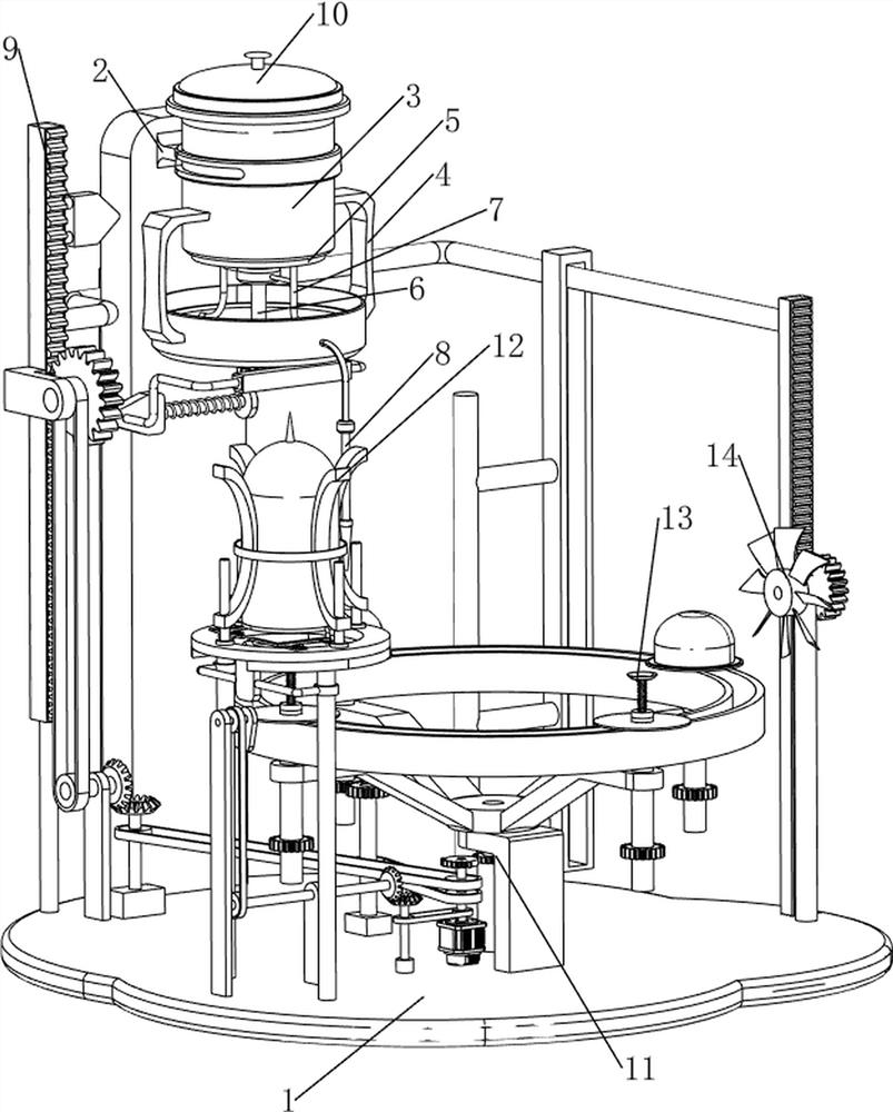
[0028] A device for painting construction helmets, such as figure 1 As shown, it includes a bottom plate 1, a first support frame 2, a paint bucket 3, a tray 4, a first baffle plate 5, a first rotating shaft 6, a hose 7, a water pipe 8, an automatic painting mechanism 9 and a flip mechanism 10, and the bottom plate 1. There is a first support frame 2 on the left side of the upper part. The first support frame 2 is provided with a paint storage bucket 3. The lower side of the paint storage bucket 3 is provided with a tray 4. The bottom of the paint storage bucket 3 is rotatably provided with a first rotating shaft 6. The first rotating shaft 6 is provided with a first baffle 5, the first baffle 5 is provided with two hoses 7, the right side of the tray 4 is provided with a water pipe 8, and the left side of the upper part of the bottom plate 1 is provided with an automatic paint spraying mechanism 9 for storing paint. Bucket 3 top is provided with flip mechanism 10.
[0029] W...
Embodiment 2
[0031] On the basis of Example 1, such as Figure 2-3As shown, the automatic painting mechanism 9 includes, the first conveyor belt 92, the second rotating shaft 93, the first bevel gear 94, the first support plate 95, the second conveyor belt 96, the first missing gear 97, the first slide rail 98, the first A tooth bar 99, the first spring 910, wedge block 911, push rod 912, the second spring 913, the second slide rail 914, the second tooth bar 915 and one-way gear 916, base plate 1 top middle is provided with motor 91, base plate 1. The upper left rotating type is provided with a second rotating shaft 93. A first conveyor belt 92 is connected between the second rotating shaft 93 and the output shaft of the motor 91. The upper left side of the bottom plate 1 is provided with a first support plate 95. The first support plate 95 The upper rotation type is provided with a first rotating rod, the first rotating rod and the second rotating shaft 93 are provided with a first bevel ...
Embodiment 3
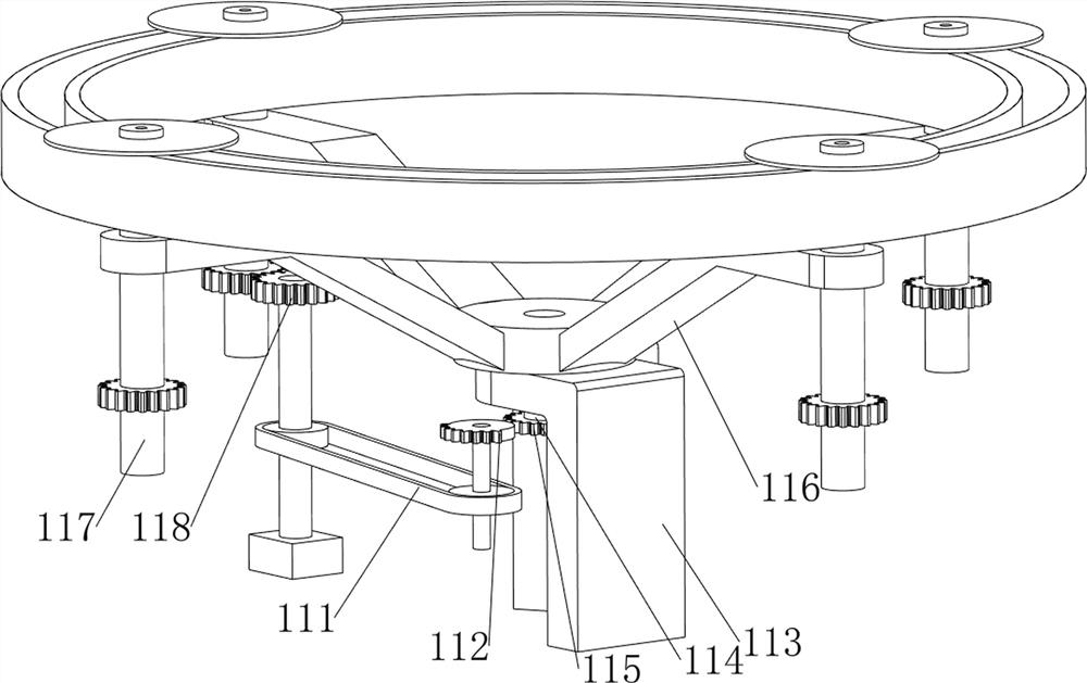
[0036] On the basis of Example 2, such as Figure 4-7 As shown, a rotating mechanism 11 is also included, and the rotating mechanism 11 includes a third conveyor belt 111, a second missing gear 112, a second support frame 113, a fourth rotating shaft 114, a second full gear 115, a rotating disk 116, and a fifth rotating shaft 117 And the 3rd full gear 118, bottom plate 1 top middle rotation type is provided with the 3rd rotating rod, the output shaft of motor 91 is provided with the second missing gear 112, is connected with the 3rd rotating rod between the 3rd rotating rod and the output shaft of motor 91. Conveyor belt 111, bottom plate 1 upper right side is provided with second support frame 113, and the second support frame 113 is provided with the 4th rotating shaft 114 of rotating type, is provided with the 2nd full gear 115 on the 4th rotating shaft 114, and the 2nd full gear 115 and The second missing gear 112 meshes, the fourth rotating shaft 114 is provided with a tu...
PUM
 Abstract
Description
Claims
Application Information
 - R&D
- Intellectual Property
- Life Sciences
- Materials
- Tech Scout
- Unparalleled Data Quality
- Higher Quality Content
- 60% Fewer Hallucinations
Browse by: Latest US Patents, China's latest patents, Technical Efficacy Thesaurus, Application Domain, Technology Topic, Popular Technical Reports.
© 2025 PatSnap. All rights reserved.Legal|Privacy policy|Modern Slavery Act Transparency Statement|Sitemap|About US| Contact US: help@patsnap.com


