Industrial batch cardboard block code imprinting facility
A technology of using batches and paper blocks, which is applied in the field of industrial batch hard paper block coding and imprinting equipment, can solve the problems of large amount of operation and low efficiency, and achieve the effect of cost saving
- Summary
- Abstract
- Description
- Claims
- Application Information
AI Technical Summary
Problems solved by technology
Method used
Image

Examples
Embodiment 1
[0047] An industrial batch of hard paper block coding stamping equipment, such as figure 1 As shown, it includes a bottom plate 1, a rotating mechanism 2 and a placement mechanism 3. The top left side of the bottom plate 1 is provided with a rotation mechanism 2, and the rotation mechanism 2 is provided with a placement mechanism 3.
[0048] The staff can place the paper block on the placing mechanism 3, start the rotating mechanism 2 to drive the placing mechanism 3 and the paper block to rotate, and cooperate with stamping. After the stamping is completed, the paper block can be taken out through the placing mechanism 3, and all stamping is completed. Stop rotating mechanism 2 operation.
Embodiment 2
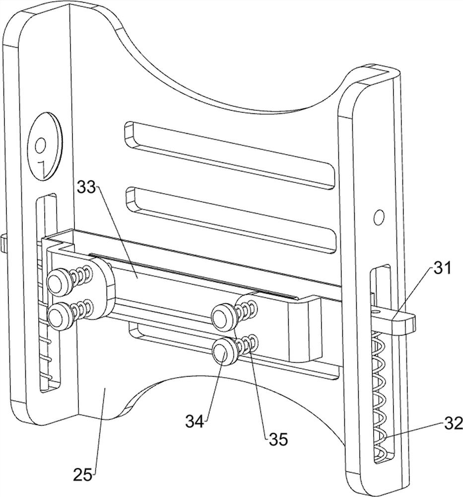
[0050] On the basis of Example 1, such as figure 2 and image 3 As shown, the rotating mechanism 2 includes a motor 21, a missing gear 22, a first rotating shaft 23, a first spur gear 24 and a turntable 25, the top of the bottom plate 1 is provided with a motor 21, and the output shaft of the motor 21 is provided with a missing gear 22, Bottom plate 1 top left side rotation type is provided with first rotating shaft 23, and first rotating shaft 23 bottom is provided with first spur gear 24, and first spur gear 24 meshes with missing gear 22, and first rotating shaft 23 top is symmetrically provided with turret 25.
[0051] Placement mechanism 3 includes placement frame 31, the first spring 32, clamp block 33, the first fixed rod 34 and the second spring 35, and the all sliding type of rotating frame 25 outsides is provided with placement frame 31, and placement frame 31 bottom front and back both sides are all slidable. The first spring 32 is connected with the turntable 25,...
Embodiment 3
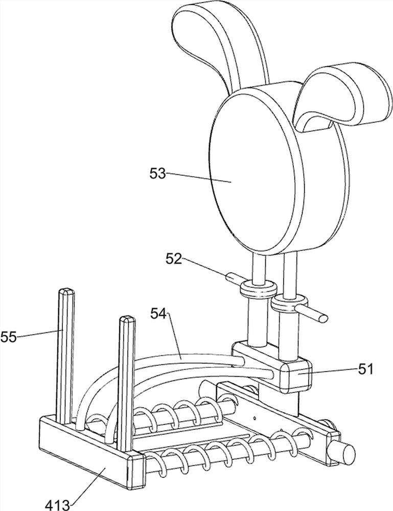
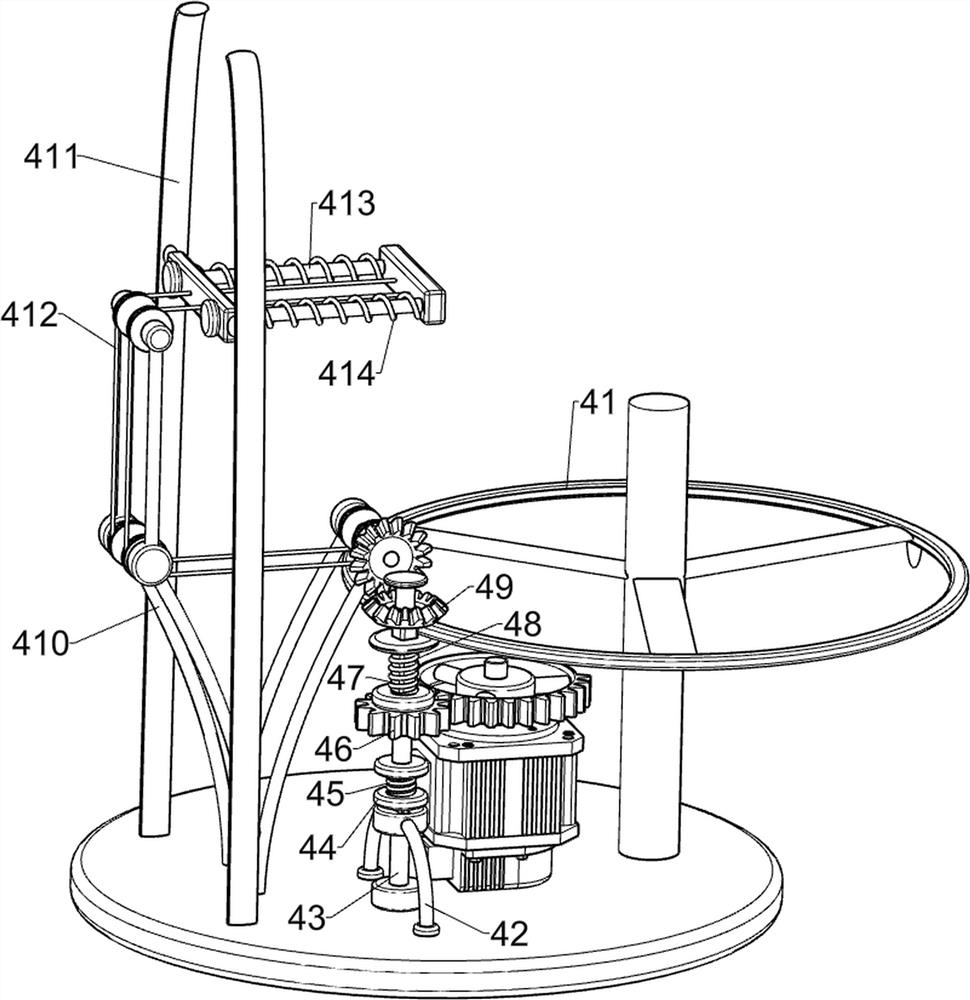
[0054] On the basis of Example 2, such as Figure 4 to Figure 6Shown, also include printing code mechanism 4, and printing code mechanism 4 includes pressure ring 41, strut bar 42, second rotating shaft 43, special-shaped tooth 44, the 3rd spring 45, the 2nd spur gear 46, telescopic bar 47, the 3rd Four springs 48, bevel tooth set 49, support frame 410, second fixed rod 411, first transmission assembly 412, printing code rod 413 and the fifth spring 414, the middle part of the first rotating shaft 23 is connected with a pressure ring 41, and the rear of the bottom plate 1 top There is a support rod 42 on the side, and a single tooth is provided on the top of the support rod 42. The upper part of the support rod 42 is rotatably provided with a second rotating shaft 43, and the middle part of the second rotating shaft 43 is provided with a short square shaft. 44, the special-shaped tooth 44 cooperates with the single tooth, the third spring 45 is connected between the top of the...
PUM
 Abstract
Description
Claims
Application Information
 - R&D
- Intellectual Property
- Life Sciences
- Materials
- Tech Scout
- Unparalleled Data Quality
- Higher Quality Content
- 60% Fewer Hallucinations
Browse by: Latest US Patents, China's latest patents, Technical Efficacy Thesaurus, Application Domain, Technology Topic, Popular Technical Reports.
© 2025 PatSnap. All rights reserved.Legal|Privacy policy|Modern Slavery Act Transparency Statement|Sitemap|About US| Contact US: help@patsnap.com