
Plate stamping bending, curling and punching forming equipment

A technology of stamping, bending and hole forming, which is applied in the field of processing machinery and equipment for one-time sequential stamping, bending, curling, punching and forming, which can solve the problems of a large number of machines and equipment, harsh working environment for workers, and large space occupation

Pending Publication Date: 2021-08-27
贵州锋锐科技有限公司
View PDF0 Cites 1 Cited by
  • Summary
  • Abstract
  • Description
  • Claims
  • Application Information

AI Technical Summary

Problems solved by technology

[0002] Although the existing stamping, bending, curling, and punching forming equipment can complete the punching, bending, curling, and punching of plates, each processing process is completed on a different machine and on a different workbench, and the workpiece transfer depends on the manipulator. or conveyor belt complete
Not only the number of machines and equipment needed to complete the entire work process is large, and the space occupied is large, but also because the transfer and placement of the workpiece and the demoulding process require time intervals, the work efficiency is low, and the noise superimposed leads to a poor working environment for workers
What's more, there will be position deviations in the process of placing semi-finished workpieces in multiple working processes, which will greatly reduce the machining accuracy and pass rate of workpieces

Method used


Image

  • Plate stamping bending, curling and punching forming equipment
  • Plate stamping bending, curling and punching forming equipment
  • Plate stamping bending, curling and punching forming equipment

Examples


Embodiment Construction

[0029] In order to realize the objectives, technical solutions and advantages of the embodiments of the present invention more clearly, the following will clearly and completely describe the technical solutions in the embodiments of the present invention in conjunction with the accompanying drawings in the embodiments of the present invention. Obviously, the described embodiments It is a part of embodiments of the present invention, but not all embodiments.

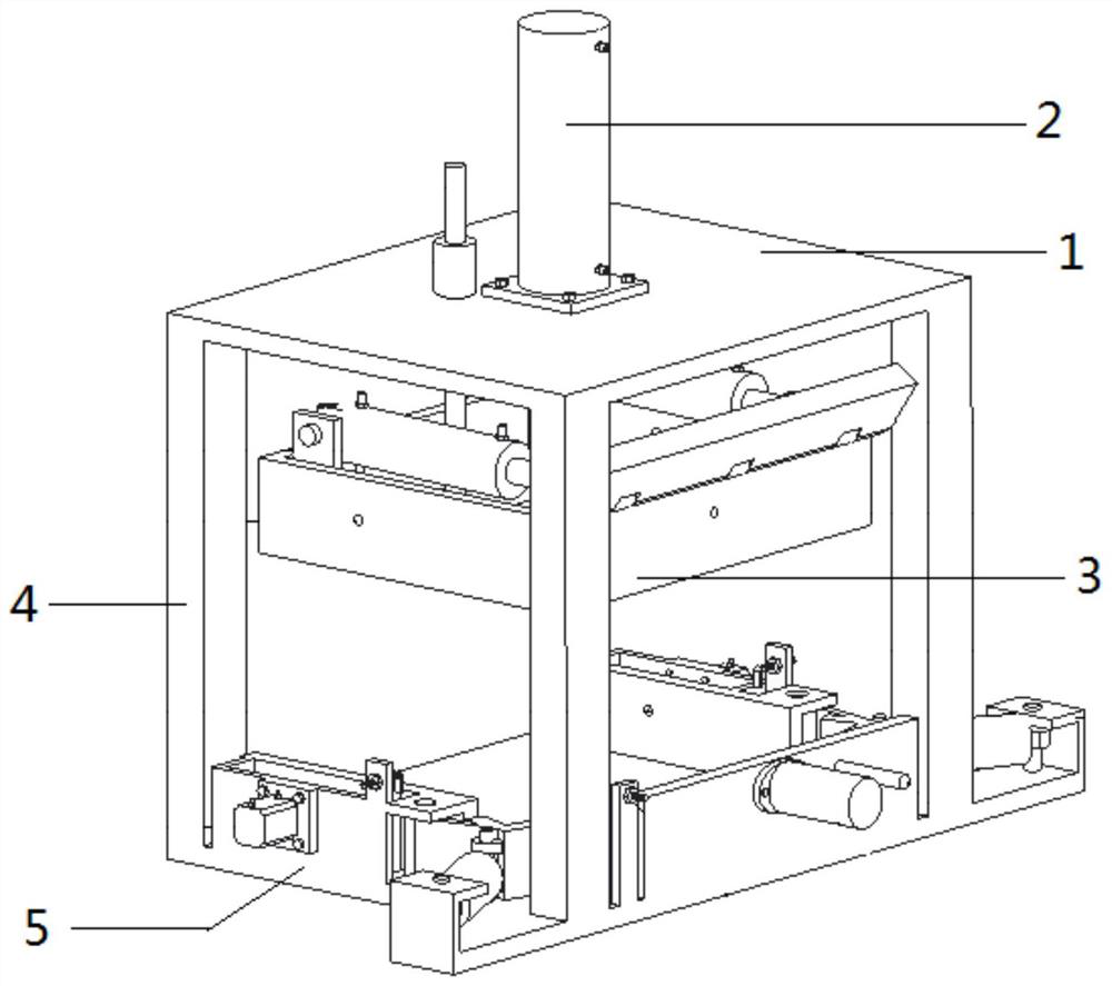
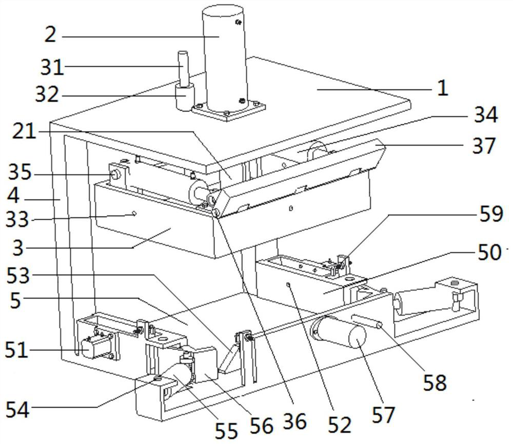
[0030] The embodiment of the present invention provides a plate stamping, bending, hemming, punching and forming equipment, refer to figure 1 , including upper plate 1, upper mold cylinder 2, upper mold 3, column 4, lower mold 5 and electro-hydraulic control system 6, which are composed of six parts.

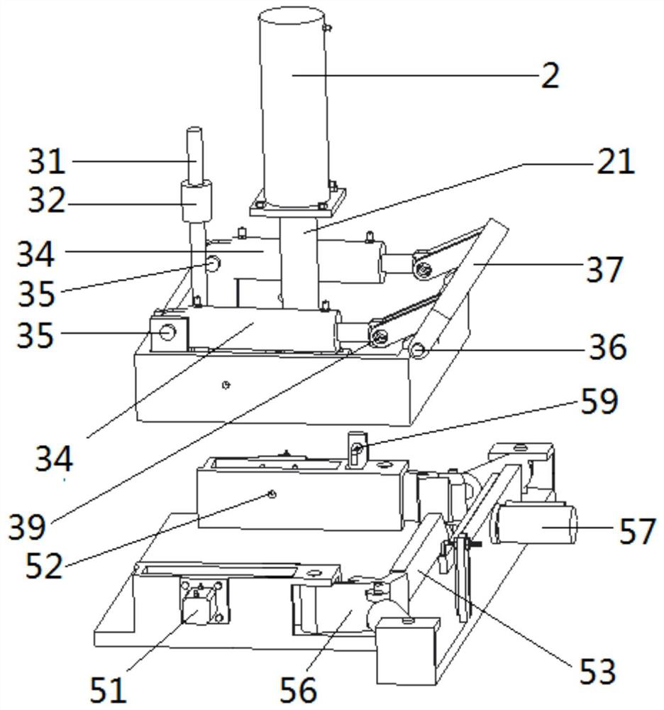
[0031] Further, refer to figure 1 and 2 , the upper plate 1 is a plate-like structure with a hole perpendicular to the plate surface in the middle, the cylinder body of the upper die cylinder 2 is fixedly connected at the...


PUM


Abstract

The invention discloses plate stamping bending, curling and punching forming equipment which comprises a supporting assembly, an upper die assembly, a lower die assembly and an electro-hydraulic control system. The supporting assembly comprises an upper plate and a stand column. The upper die assembly comprises an upper die oil cylinder, an upper die, an upper edge folding die oil cylinder and an upper edge folding die, and the upper edge folding die and the upper edge folding die oil cylinder are rotationally installed on the upper die. The lower die assembly comprises a side die, a lower rear die, a side hole oil cylinder, a lower edge folding oil cylinder, a lower edge folding die, a rear shaping punching oil cylinder, a rear shaping die and a positioning pin. The electro-hydraulic control system comprises an electric control chip, a power relay and electromagnetic directional valves. A microcomputer module outputs sequential control currents and controls the corresponding electromagnetic directional valves to act, then high-pressure liquid flow is controlled to enter and exit from corresponding working oil cylinders, stamping bending, curling shaping and punching operation of workpieces is completed in sequence, all the machining processes are completed on the same workbench, one machine completes the machining steps of multiple machines, the problems of occupied space and purchase cost are solved, the machining precision and the qualified rate of the workpieces are improved, machining noise is lowered, and the working environment of workers is improved.

Description

technical field [0001] The invention relates to the mechanical field of plate stamping, bending, curling, and forming equipment, and in particular to a processing mechanical equipment for one-time sequential stamping, bending, curling, and forming. Background technique [0002] Although the existing punching, bending, curling, and punching forming equipment can complete the punching, bending, curling, and punching of plates, each processing process is completed on a different machine and on a different workbench, and the workpiece transfer depends on the manipulator. or conveyor belt complete. Not only the number of machines and equipment needed to complete the entire work process is large, and the space occupied is large, but also because the transfer and placement of the workpiece and the demoulding process require time intervals, the work efficiency is low, and the noise superposition leads to a poor working environment for workers. What's more, in the process of placing...

Claims


Application Information

Patent Timeline
IPC IPC(8): B21D37/10B21D37/12B21D19/08B21D28/34B21D35/00
CPCB21D37/10B21D37/12B21D19/08B21D28/34B21D35/001
Inventor 唐孟华
Owner 贵州锋锐科技有限公司
Learn More