Pavement marking equipment for constructional engineering
A technology for scribing equipment and construction engineering, applied in buildings, roads, roads, etc., can solve the problems of uneven moving speed of scribing equipment, accumulation or leakage of paint at the scribing part, troublesome operation, etc. Small, uniform speed, simple operation effect
- Summary
- Abstract
- Description
- Claims
- Application Information
AI Technical Summary
Problems solved by technology
Method used
Image
Examples
Embodiment 1
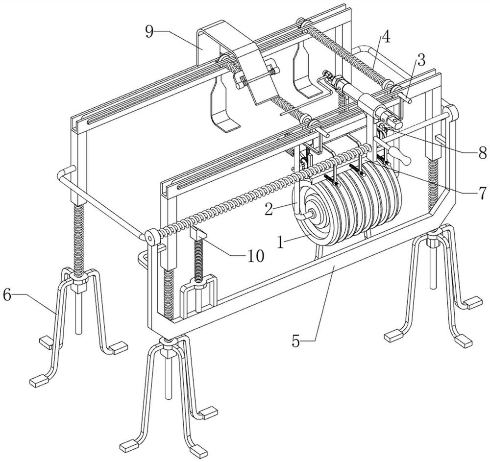
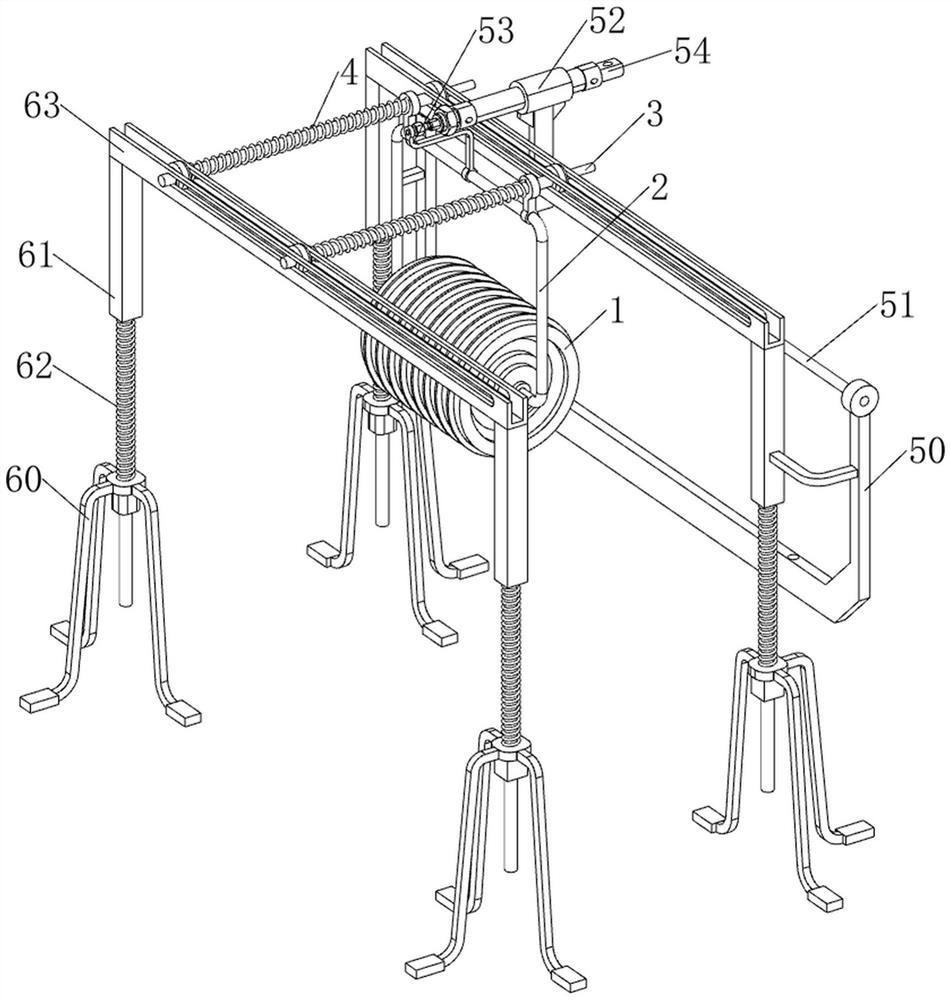
[0060] A road surface marking device for construction engineering, such as figure 1 and figure 2 As shown, it includes a cable wheel 1, a connecting rod 2, a guide rod 3, a first spring 4, a moving mechanism 5 and a lifting mechanism 6, the lifting mechanism 6 is provided with a moving mechanism 5, and the lifting mechanism 6 is slidingly provided with two guides. The connecting rod 2 is slidingly arranged between the front side of the rod 3 and the guide rod 3, and the lower part of the connecting rod 2 is rotatably provided with a wire wheel 1, and the first spring 4 is arranged between the rear side of the upper part of the connecting rod 2 and the two guide rods 3 .
[0061] Lifting mechanism 6 comprises supporting pin 60, connecting block 61, second spring 62 and slide rail 63, and four supporting pins 60 tops are provided with connecting block 61 slidingly in the middle, connecting block 61 top and supporting pin 60 tops on the same side A second spring 62 is provided...
Embodiment 2
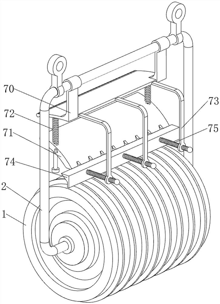
[0065] On the basis of Example 1, such as figure 1 , image 3 , Figure 4 and Figure 5 As shown, a cleaning mechanism 7 is also included, and the cleaning mechanism 7 includes a fixed plate 70, a cleaning plate 71, a third spring 72, a guide plate 73, a stopper 74 and a fourth spring 75, and the connecting rod 2 top is provided with a fixed plate 70 , the bottom of the fixed plate 70 is slidingly provided with a cleaning plate 71, the cleaning plate 71 cooperates with the wire wheel 1, a third spring 72 is arranged between the left and right sides of the top of the cleaning plate 71 and the fixed plate 70, and the upper part of the front side of the fixed plate 70 is spaced Three guide plates 73 are provided, and stoppers 74 are slidably arranged between the lower parts of the guide plates 73, and the stoppers 74 cooperate with the cleaning plate 71, and fourth springs 75 are arranged between the stoppers 74 and the three guide plates 73.
[0066] Also include reset mechan...
Embodiment 3
[0069] On the basis of Example 2, such as figure 1 , Figure 6 and Figure 7 As shown, a trigger mechanism 9 is also included, and the trigger mechanism 9 includes a mounting plate 90, a rotating plate 91, a torsion spring 92 and a fixed rod 93, and the middle of the top of the slide rail 63 on the rear side is provided with a mounting plate 90, and the front side of the mounting plate 90 Bottom rotary type is provided with rotating plate 91, and torsion spring 92 is all provided with between rotating plate 91 left and right sides and mounting plate 90, and the telescoping rod rear side of cylinder 54 is provided with fixed rod 93, and fixed rod 93 cooperates with rotating plate 91, The fixing rod 93 is located at the front side of the connecting plate 53 .
[0070] When people control the extension of the telescopic rod of the cylinder 54, it drives the connecting plate 53, the connecting rod 2, the wire wheel 1 and the fixed rod 93 to move backward, thereby completing the ...
PUM
 Abstract
Description
Claims
Application Information
 - R&D
- Intellectual Property
- Life Sciences
- Materials
- Tech Scout
- Unparalleled Data Quality
- Higher Quality Content
- 60% Fewer Hallucinations
Browse by: Latest US Patents, China's latest patents, Technical Efficacy Thesaurus, Application Domain, Technology Topic, Popular Technical Reports.
© 2025 PatSnap. All rights reserved.Legal|Privacy policy|Modern Slavery Act Transparency Statement|Sitemap|About US| Contact US: help@patsnap.com


