Check patentability & draft patents in minutes with Patsnap Eureka AI!

Waste heat fan heater and working method thereof

A heater and waste heat technology, applied in heat exchangers, air heaters, fluid heaters, etc., can solve the problems of heat recovery and utilization without hot fluid, direct or indirect discharge to the ground or the atmosphere, energy waste, etc., to achieve Increase the area and heat exchange time, overcome pressure loss and kinetic energy loss, and save energy

Pending Publication Date: 2021-08-27
重庆奇螺机械制造有限公司
View PDF0 Cites 2 Cited by
  • Summary
  • Abstract
  • Description
  • Claims
  • Application Information

AI Technical Summary

Problems solved by technology

At present, this part of the thermal fluid is generally cooled by cooling medium such as circulating cooling water or ground air, and then the cooling medium is directly or indirectly discharged to the ground or the atmosphere; in this process, the heat of the thermal fluid is basically not recycled; resulting in a certain Energy waste

Method used


Image

  • Waste heat fan heater and working method thereof
  • Waste heat fan heater and working method thereof
  • Waste heat fan heater and working method thereof

Examples


Embodiment Construction

[0027] The following will clearly and completely describe the technical solutions in the embodiments of the present invention with reference to the accompanying drawings in the embodiments of the present invention. Obviously, the described embodiments are only some, not all, embodiments of the present invention. Based on the embodiments of the present invention, all other embodiments obtained by persons of ordinary skill in the art without making creative efforts belong to the protection scope of the present invention.

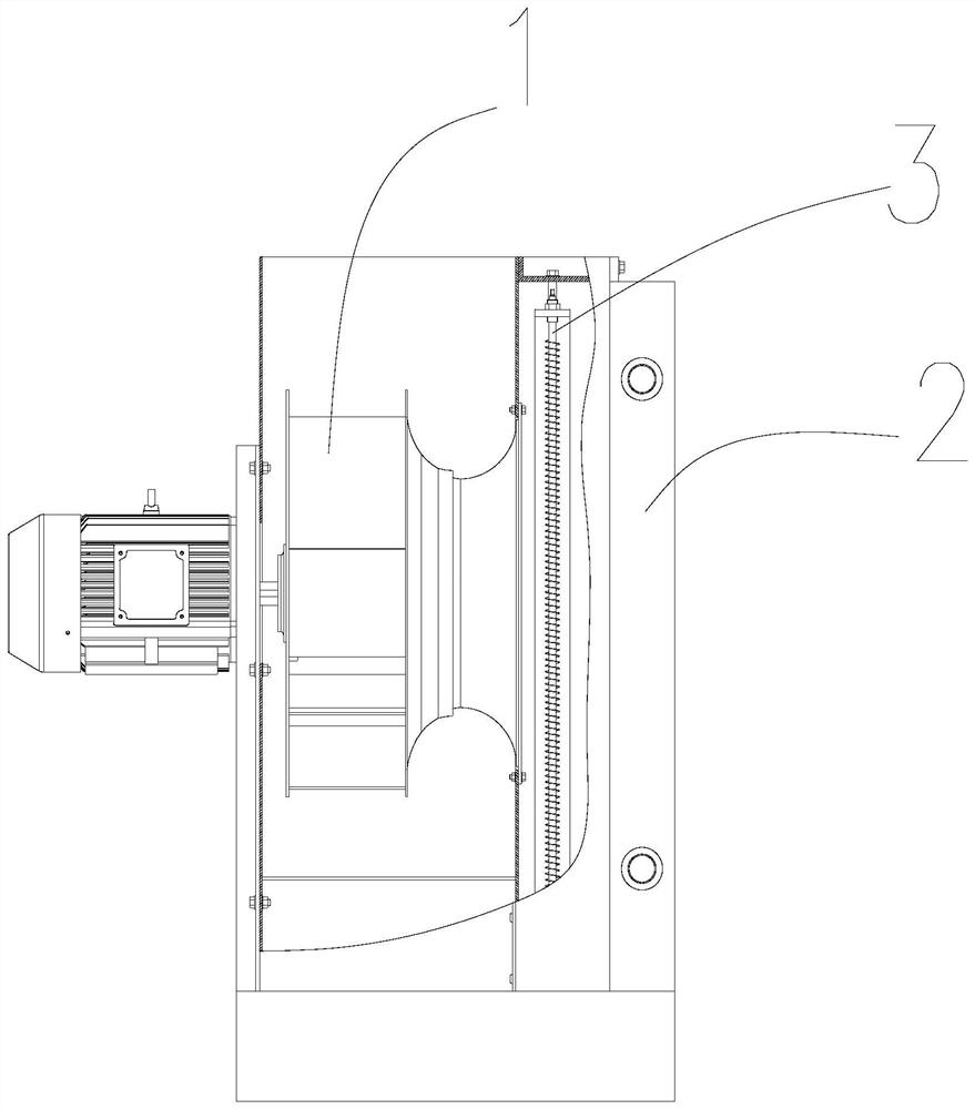
[0028] like figure 1 Shown is the overall structure diagram of the present invention, the specific structure is, a waste heat heater 1, including a fan 1, a heater 3 and a heat exchanger 2, the inlet of the heater 3 is connected to the outlet of the heat exchanger 2 The gas port is connected, and the gas outlet of the heater 3 is connected with the air inlet of the fan 1;

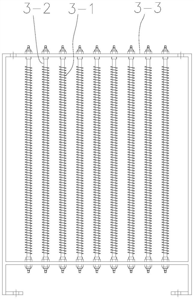
[0029] like image 3 Shown is the structural diagram of the heat exchanger. The heat ...


PUM


Abstract

The invention discloses a waste heat fan heater. The waste heat fan heater is characterized in that the waste heat fan heater comprises a fan, a heater and a heat exchanger; an air inlet of the heater is communicated with an air outlet of the heat exchanger, and an air outlet of the heater is communicated with an air inlet of the fan; the heat exchanger comprises a shell and an airflow channel, and an oil inlet, an oil outlet, an air inlet and an air outlet are formed in the shell; and air flow channels are evenly distributed in the shell, a heat flow channel is formed between every two adjacent air flow channels, inlets of the air flow channels are communicated with the air inlet, outlets of the air flow channels are communicated with the air inlet of the fan, inlets of the heat flow channels are communicated with the oil inlet, and oil outlets of the heat flow channels are communicated with the oil outlet of the shell. Waste heat is utilized, energy is saved, and the energy consumption is about 2-10% of that of an existing pure electric fan heater under the condition that the waste heat can be completely utilized to meet the requirements for the temperature and the flow of warm air.

Description

technical field [0001] The invention relates to the field of waste heat utilization, in particular to a waste heat heater and a working method thereof. Background technique [0002] In the production process of the enterprise, some mechanical equipment produces liquid with a temperature of 60-150°C or gas with a temperature of 90-280°C during the working process. In this paper, this part of the higher liquid or gas is called thermal fluid. At present, this part of the thermal fluid is generally cooled by cooling medium such as circulating cooling water or ground air, and then the cooling medium is directly or indirectly discharged to the ground or the atmosphere; in this process, the heat of the thermal fluid is basically not recycled; resulting in a certain Energy waste. Therefore, in order to solve the above-mentioned problems, a new device is needed to effectively utilize the energy. Contents of the invention [0003] Aiming at the deficiencies of the prior art, the p...

Claims


Application Information

Patent Timeline
Patent Type & Authority Applications(China)
IPC IPC(8): F24H3/04F24H9/00F24H9/18F28D21/00
CPCF24H3/0405F24H9/0052F24H9/1863F28D21/0008
Inventor 彭期林张光燕王汝强严富权
Owner 重庆奇螺机械制造有限公司
Features
  • R&D
  • Intellectual Property
  • Life Sciences
  • Materials
  • Tech Scout
  • Unparalleled Data Quality
  • Higher Quality Content
  • 60% Fewer Hallucinations
Learn More