
High-voltage transmission line monitor and monitoring system with same

A technology of high-voltage transmission lines and monitoring systems, which is applied in radio wave measurement systems, signal transmission systems, satellite radio beacon positioning systems, etc., can solve problems such as inability to perform repairs and maintenance in a timely manner, and difficulty in reporting fault monitoring information. , to achieve the effect of less intermediate nodes, high-speed and reliable information transmission

Pending Publication Date: 2021-08-27
安信电力(安徽)有限公司
View PDF0 Cites 0 Cited by
  • Summary
  • Abstract
  • Description
  • Claims
  • Application Information

AI Technical Summary

Problems solved by technology

In this way, it is difficult to report fault monitoring information in areas not covered by the GSM or GPRS mobile communication transmission network, resulting in failure to perform repairs and maintenance in time when high-voltage transmission line faults occur in this area

Method used


Image

  • High-voltage transmission line monitor and monitoring system with same
  • High-voltage transmission line monitor and monitoring system with same
  • High-voltage transmission line monitor and monitoring system with same

Examples


Embodiment 1

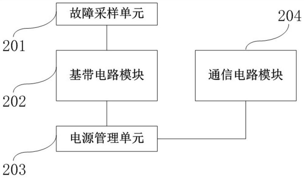
[0014] Such as figure 1 As shown, this embodiment provides a high-voltage transmission line monitor 301, including a housing, a circuit board, a fastening device, a baseband circuit module 202 and a communication circuit module 204; the circuit board is arranged inside the housing, and the The baseband circuit module 202 and the communication circuit module 204 are arranged on the circuit board and realize circuit connection through the circuit board; the fastening device is arranged on the top of the housing; the communication circuit module 204 is a GLONASS communication module or a GPS communication module Or BDS RDSS communication module or BDS RNSS communication module or EnOcean communication module or Zigbee communication module or Z-Wave communication module. Those skilled in the art can understand, owing to adopt GPS communication module or BDS RDSS communication module or BDS RNSS communication module or EnOcean communication module or Zigbee communication module or ...

Embodiment 2

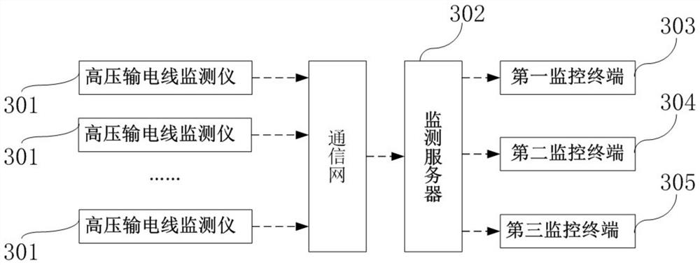
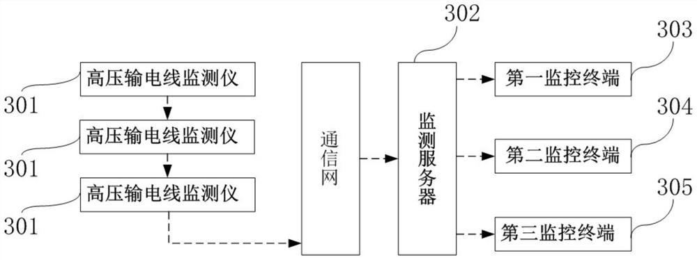
[0021] Such as figure 2 or image 3 As shown, the present embodiment provides a high-voltage transmission line monitoring system, including a high-voltage transmission line monitor 301 and a monitoring server 302; the high-voltage transmission line monitor 301 is suspended on the high-voltage transmission line; the monitoring server 302 is a cloud server ; The high-voltage transmission line monitoring instrument 301 and the monitoring server 302 realize a communication connection. Those skilled in the art can understand that a high-voltage transmission line monitor 301 is suspended every 30 meters to 50 meters along the high-voltage transmission line; each high-voltage transmission line monitor 301 has a unique identification code and is stored in the In the monitoring server 302 described above, when the monitoring server 302 receives the fault information sent by the high-voltage transmission line monitor 301, it can quickly locate and identify it, so that it is convenient...


PUM


Abstract

The invention discloses a high-voltage transmission line monitor and a monitoring system with the same. The high-voltage transmission line monitor comprises a shell, a circuit board, a fastening device, a baseband circuit module (202) and a communication circuit module (204); the circuit board is arranged in the shell, and the baseband circuit module (202) and the communication circuit module (204) are arranged on the circuit board and are in circuit connection through the circuit board; the fastening device is arranged at the top of the shell; the communication circuit module (204) is a GLONASS communication module or a GPS communication module or a BDS RDSS communication module or a BDS RNSS communication module or an EnOcean communication module or a Zigbee communication module or a Z-Wave communication module. According to the invention, the detector can still work continuously in an area which is not covered by a GSM or GPRS mobile communication transmission network.

Description

technical field [0001] The invention relates to the technical field of energy and power transmission, in particular to a high-voltage transmission line monitor and a monitoring system with the monitor. Background technique [0002] High-voltage power transmission is a way of boosting the output voltage of the generator through a transformer in a power plant and then transmitting it. The reason why this way is used for power transmission is that under the same power transmission power, the higher the voltage, the smaller the current. Power transmission can reduce the current during power transmission, thereby reducing the heat loss caused by the current and reducing the material cost of long-distance power transmission. Common faults of high-voltage transmission lines include high-resistance leakage faults, high-resistance flashover faults, and open circuit or open circuit faults. On the one hand, the monitoring of high-voltage transmission lines requires timely detection of ...

Claims


Application Information

Patent Timeline
Patent Type & Authority Applications(China)
IPC IPC(8): G01R31/08G01R31/52G01R31/54G01R31/58G01S19/33G08C17/02H02J7/35
CPCG01R31/085G01S19/33G08C17/02G01R31/52G01R31/54G01R31/58H02J7/35
Inventor 王蓉
Owner 安信电力(安徽)有限公司
Learn More