Self-locking electric stockbridge damper
A shock-proof hammer and self-locking technology, applied in the direction of mechanical vibration attenuation devices, etc., can solve problems such as risks in the installation process, and achieve the effect of simple installation process and convenient connection
- Summary
- Abstract
- Description
- Claims
- Application Information
AI Technical Summary
Problems solved by technology
Method used
Image
Examples
Embodiment 1
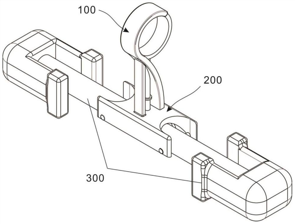
[0031] refer to figure 1 , which is the first embodiment of the present invention, provides a self-locking electric anti-vibration hammer, the anti-vibration hammer includes a clamp unit 100, a connection unit 200 and a hammer head unit 300; wherein, the clamp unit 100 is an anti-vibration hammer The part used to clamp the power cable, that is, the head of the anti-vibration hammer, and the connection unit 200 is used to connect the hammer unit 300, and the connection assembly 202 in the connection unit 200 can be used to transmit power to limit the clamp unit 100 The clamping state; the hammer head unit 300 is the hammer head style of a traditional anti-vibration hammer, which is used to reduce the vibration existing on the power cable. Further, the hammer head unit 300 is used to provide the driving force when the wire clamp unit 100 is clamped , The difference from the traditional anti-vibration hammer is that the hammer heads at both ends are split structures.
[0032] Sp...
Embodiment 2
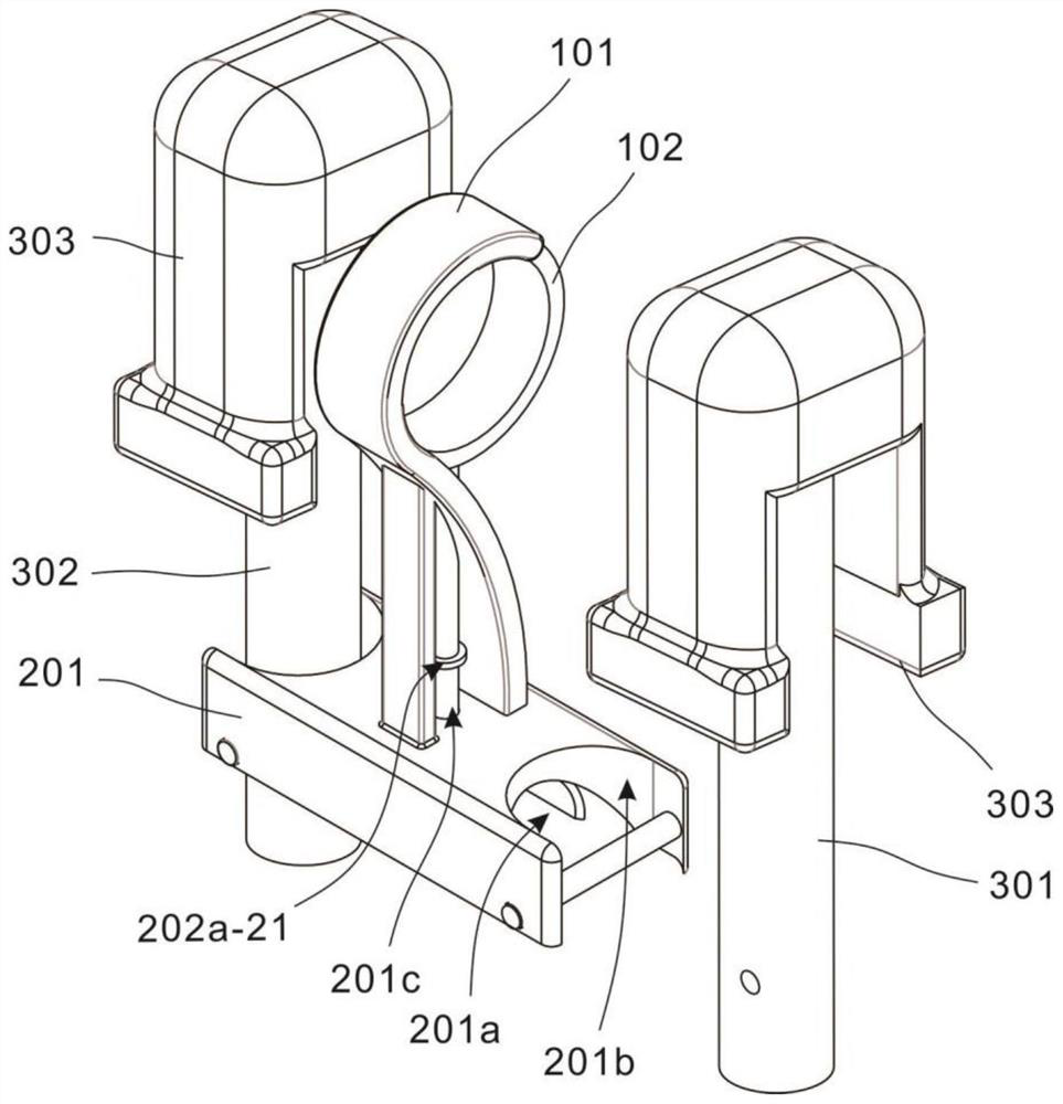
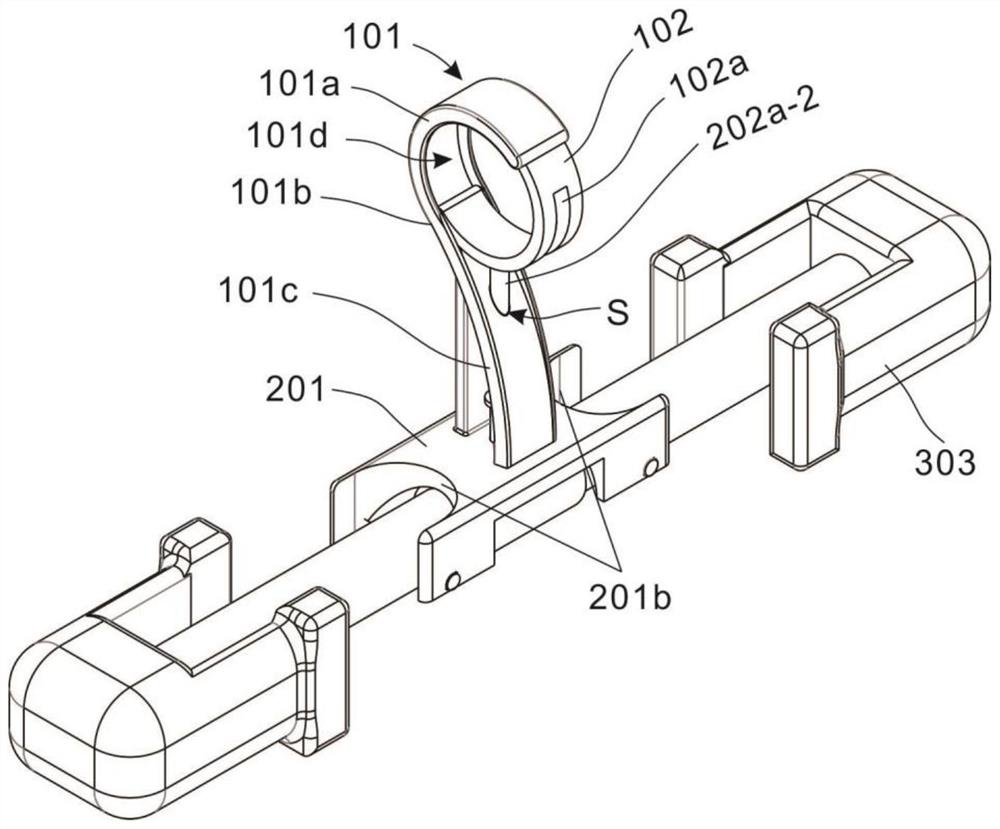
[0036] refer to Figure 2~4 , is the second embodiment of the present invention, and this embodiment is different from the first embodiment in that: the whole of the wire clamp hook 101 is divided into a bending part 101a, a neck 101b and a connecting part 101c from top to bottom, wherein, The curved portion 101a is in the shape of a semi-circular ring in the radial direction, and a limiting groove 101d is opened in the side wall of the inner ring, and the limiting groove 101d starts from the end of the curved portion 101a, and is finally flush with the bottom of the connecting portion 101c; the connecting portion 101c is fixed on the top of the connection housing 201 .
[0037]The cladding plate 102 is in the shape of a semicircle in the radial direction, one end of which is hinged in the groove of the neck 101b, and the other end is mated and connected in the limiting groove 101d; the outer ring side wall of the cladding plate 102 is provided with a limiting arc groove 102a ...
Embodiment 3
[0042] refer to Figure 2-5 , which is the third embodiment of the present invention. This embodiment is different from the second embodiment in that: a mounting groove 201a is opened in the side wall of the lower end of the connection housing 201, and limiting grooves 201b are symmetrically opened on the side walls of both ends. , and a connecting hole 201c is opened on the side wall of the middle part thereof.
[0043] The connection assembly 202 includes a driving part 202a and a connecting part 202b, both of which are mated and connected. One end of the driving part 202a is located in the installation groove 201a, the other end extends in the wire clip hook 101, and the connecting part 202b is arranged in the installation groove 201a.
[0044] The driver 202a includes an arc-shaped drive plate 202a-1 and a drive rod 202a-2 connected to the top side wall of the arc-shaped drive plate 202a-1, wherein the arc-shaped drive plate 202a-1 is located in the installation groove 201...
PUM
 Abstract
Description
Claims
Application Information
 - R&D
- Intellectual Property
- Life Sciences
- Materials
- Tech Scout
- Unparalleled Data Quality
- Higher Quality Content
- 60% Fewer Hallucinations
Browse by: Latest US Patents, China's latest patents, Technical Efficacy Thesaurus, Application Domain, Technology Topic, Popular Technical Reports.
© 2025 PatSnap. All rights reserved.Legal|Privacy policy|Modern Slavery Act Transparency Statement|Sitemap|About US| Contact US: help@patsnap.com


