Supercharge Your Innovation With Domain-Expert AI Agents!

Brushless direct current motor rotor positioning method and brushless direct current motor

A technology of brushed DC motor and positioning method, which is applied in the direction of electronic commutation motor control, electrical components, control system, etc., can solve the problems of failure to start, easy to fail to start, difficult to accurately judge the rotor, etc., and achieve the effect of improving reliability

Active Publication Date: 2021-08-27
SHENZHEN TOPBAND CO LTD
View PDF4 Cites 0 Cited by
  • Summary
  • Abstract
  • Description
  • Claims
  • Application Information

AI Technical Summary

Problems solved by technology

The back electromotive force of the motor is proportional to the speed of the motor. When the motor is stationary or the speed is very low, the back electromotive force amplitude is zero or very small. It is difficult to accurately judge the position of the rotor, which may lead to startup failure, especially when starting with load. Very prone to startup failures

Method used


Image

  • Brushless direct current motor rotor positioning method and brushless direct current motor
  • Brushless direct current motor rotor positioning method and brushless direct current motor
  • Brushless direct current motor rotor positioning method and brushless direct current motor

Examples


Embodiment Construction

[0066] In order to have a clearer understanding of the technical features, purposes and effects of the present invention, the specific implementation manners of the present invention will now be described in detail with reference to the accompanying drawings.

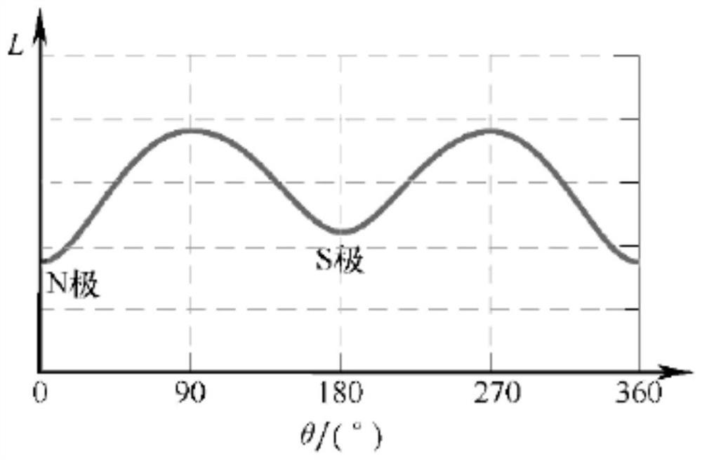
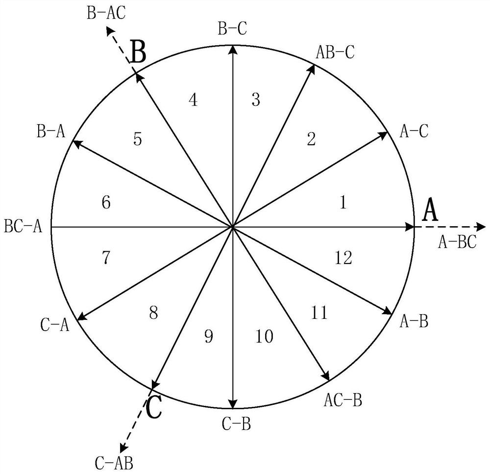
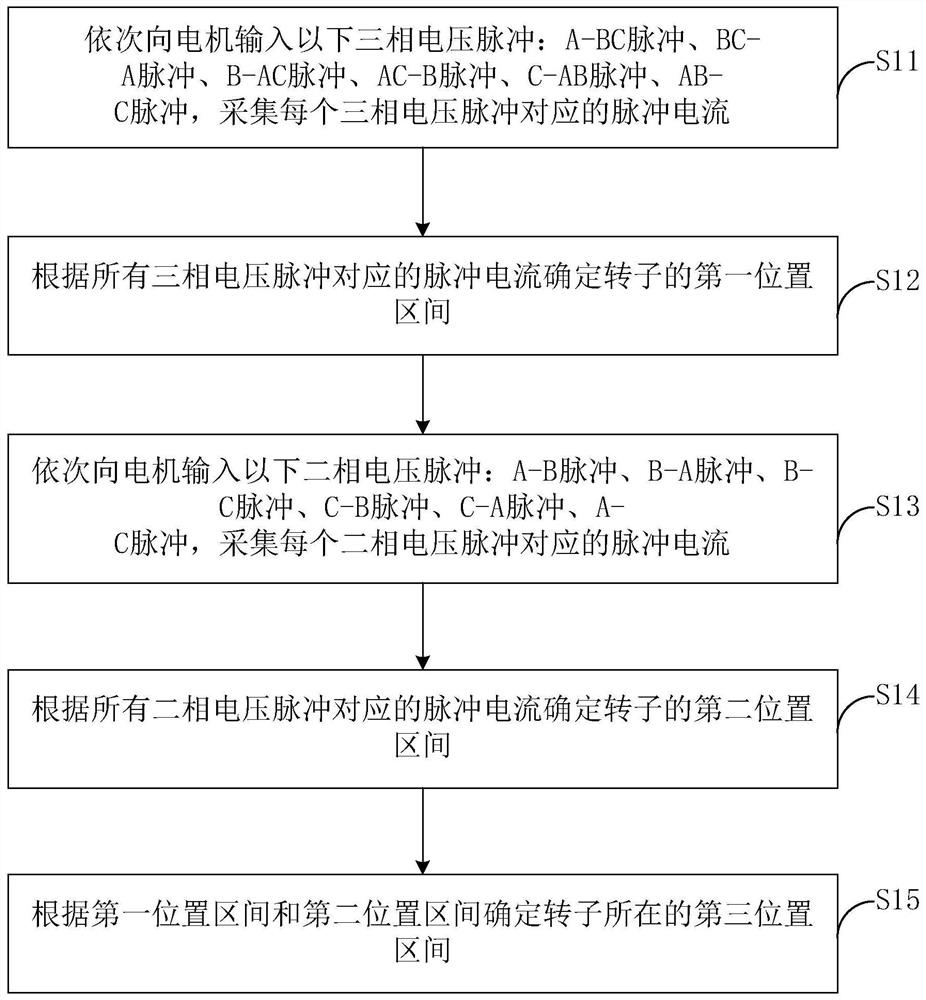
[0067] In a preferred embodiment, refer to Figure 1 to Figure 3 , The brushless DC motor rotor positioning method of this embodiment is applied to the brushless DC motor, the brushless DC motor includes A phase, B phase and C phase, and the A phase, B phase and C phase are separated by 120°. The brushless DC motor has the saturation effect of the stator core, which leads to a certain correspondence between the inductance of the motor winding and the position of the rotor. Therefore, the initial position of the rotor can be obtained indirectly by detecting the inductance of the stator winding. When a short-term voltage detection pulse with the same pulse width is applied to the stator winding, the rising speed of the cu...


PUM


Abstract

The invention relates to a brushless direct current motor rotor positioning method and a brushless direct current motor. The method comprises the following steps: S11, inputting a preset three-phase voltage pulse group into a motor in sequence, and collecting pulse current corresponding to each three-phase voltage pulse; S12, determining a first position interval of the rotor according to the pulse current corresponding to all the three-phase voltage pulses; S13, inputting a preset two-phase voltage pulse group to the motor in sequence, and collecting pulse current corresponding to each two-phase voltage pulse; S14, determining a second position interval of the rotor according to the pulse current corresponding to all the two-phase voltage pulses; and S15, determining a third position interval where the rotor is located according to the first position interval and the second position interval. Accurate positioning of the rotor is achieved under the condition of no position sensor, follow-up smooth starting is ensured, and the reliability of the brushless direct current motor controller is improved.

Description

technical field [0001] The invention relates to the field of brushless direct current motors, and more specifically relates to a method for positioning the rotor of a brushless direct current motor and the brushless direct current motor. Background technique [0002] For brushless DC motors, the controller needs to turn on the corresponding motor phases according to the position of the rotor to start the motor. In order to obtain the rotor position information, a position sensor is installed on the motor in the prior art, but the installation of the sensor not only leads to an increase in cost, but also has problems with machining accuracy. If the processing accuracy is not enough, the position deviation of the sensor will cause the commutation error of the motor, and even damage the controller. [0003] In the prior art, there have been brushless DC motor controllers that do not use position sensors. Under the condition of no position sensor, the motor positioning principl...

Claims


Application Information

Patent Timeline
IPC IPC(8): H02P6/185H02P6/20H02P6/22
CPCH02P6/185H02P6/20H02P6/22
Inventor 何舟
Owner SHENZHEN TOPBAND CO LTD
Features
  • R&D
  • Intellectual Property
  • Life Sciences
  • Materials
  • Tech Scout
  • Unparalleled Data Quality
  • Higher Quality Content
  • 60% Fewer Hallucinations
Learn More