
Synchronization signal sending method, electronic equipment and storage medium

A technology for synchronizing signals and sending methods, which is applied in the field of communication, and can solve the problems of not knowing the antenna port information of the base station, the influence of the successful rate of terminal demodulation of NPSS and NSSS sequences, and the decline of autocorrelation

Pending Publication Date: 2021-08-27
ZTE CORP
View PDF0 Cites 0 Cited by
  • Summary
  • Abstract
  • Description
  • Claims
  • Application Information

AI Technical Summary

Problems solved by technology

[0003] The inventors of the present application found that because the design of the primary synchronization signal NPSS and secondary synchronization signal NSSS on the base station side is different from that of other physical layer signals, the terminal does not know the NPSS and secondary synchronization signal NSSS on the base station side when demodulating the narrowband primary synchronization signal NPSS and the narrowband secondary synchronization signal NSSS. Antenna port information, so the narrowband primary synchronization signal NPSS and the narrowband secondary synchronization signal NSSS sent by the two antennas on the base station side are identical signals in the time-frequency domain. The synchronization signals sent by the two antennas of the base station pass through the space wireless channel and are superimposed on the terminal antenna. At the terminal antenna, when the phases of the two signals are opposite, the signal strength of the superimposed signal drops sharply, and the signal-to-noise ratio of NPSS / NSSS will become lower. Since the sequence length of NPSS and NSSS is relatively short, in low signal-to-noise ratio scenarios Under this condition, the autocorrelation of NPSS and NSSS sequences will be severely reduced, which will have a serious impact on the success rate of terminal demodulation of NPSS and NSSS sequences

Method used


Image

  • Synchronization signal sending method, electronic equipment and storage medium
  • Synchronization signal sending method, electronic equipment and storage medium
  • Synchronization signal sending method, electronic equipment and storage medium

Examples


Embodiment Construction

[0023] In order to make the purpose, technical solutions and advantages of the embodiments of the present invention more clear, various implementation modes of the present invention will be described in detail below in conjunction with the accompanying drawings. However, those of ordinary skill in the art can understand that, in each implementation manner of the present invention, many technical details are provided for readers to better understand the present application. However, even without these technical details and various changes and modifications based on the following implementation modes, the technical solutions claimed in this application can also be realized. The division of the following embodiments is for the convenience of description, and should not constitute any limitation to the specific implementation of the present invention, and the various embodiments can be combined and referenced to each other on the premise of no contradiction.

[0024] The first emb...


PUM


Abstract

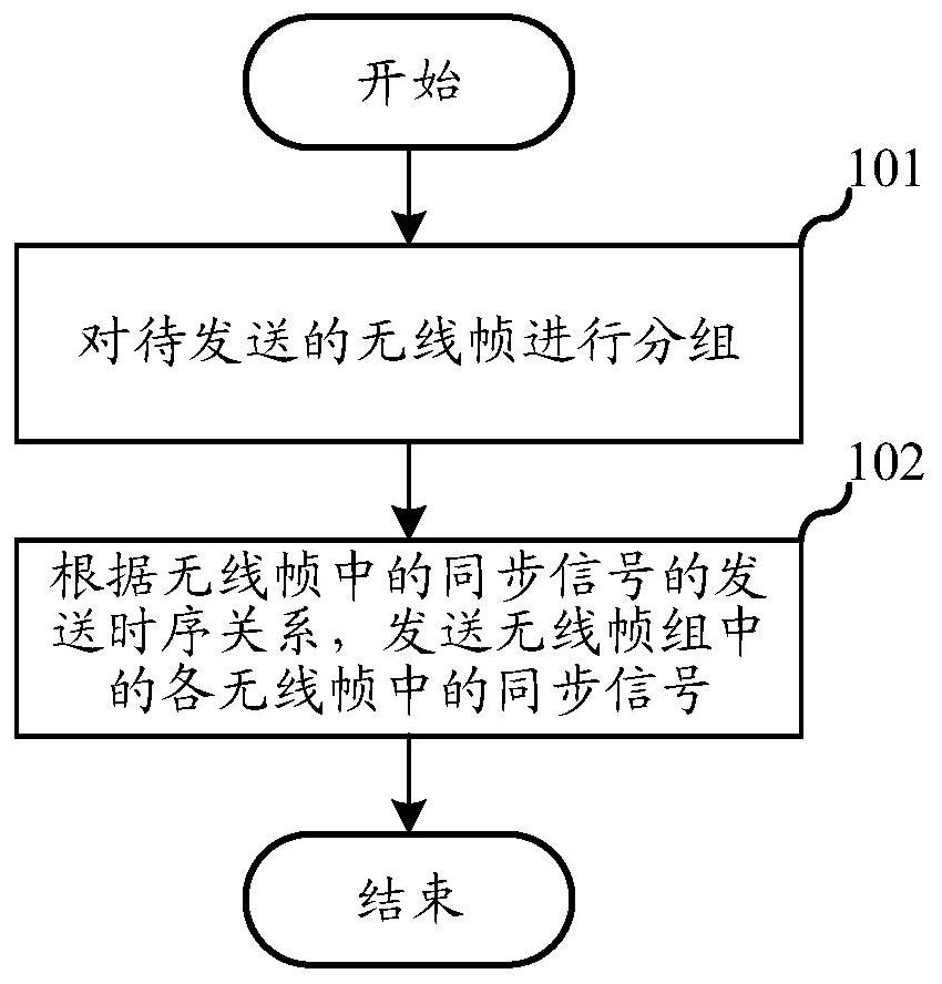
The embodiment of the invention relates to the technical field of communication, and discloses a synchronization signal sending method, electronic equipment and a storage medium. In the invention, the method comprises the following steps of: grouping wireless frames to be sent to obtain a plurality of wireless frame groups; and sending each wireless frame group through a first antenna port and a second antenna port, and sending a synchronization signal in at least one wireless frame in each wireless frame group only through the first antenna port or the second antenna port. Wireless frames are sent in groups at the first antenna port and the second antenna port, and a synchronization signal in at least one wireless frame is sent only through the first antenna port or the second antenna port, so that the autocorrelation of the synchronization signal received by a terminal is prevented from being reduced under the condition that the terminal does not perceive, and the user experience is improved. And the possibility of signal demodulation failure of the terminal is reduced.

Description

technical field [0001] The embodiments of the present invention relate to the technical field of communication, and in particular, to a method for sending a synchronization signal, an electronic device, and a storage medium. Background technique [0002] At present, in the application scenario of NB-IoT technology, when NB-IoT devices access the network, they first need to search for the primary and secondary synchronization information of the cell, and only after the time-frequency domain synchronization between the terminal and the base station is completed can the system messages of the cell be demodulated. Cell access, so demodulating primary and secondary synchronization is a key step for a terminal to access a cell. In the third-generation cooperation project 3GPP, the downlink channel of NB-IOT narrowband Internet of Things is required to support two antenna ports, but due to cost reasons and power consumption requirements, most terminals receive with a single antenna...

Claims


Application Information

Patent Timeline
IPC IPC(8): H04W56/00
CPCH04W56/003H04W56/0015H04L5/0048
Inventor 崔晓光杨锋未艳增
Owner ZTE CORP
Learn More