Industrial automatic part cleaning device

An automatic cleaning and industrial technology, applied in cleaning methods using tools, cleaning methods using liquids, transportation and packaging, etc., can solve problems such as low efficiency and high labor intensity

Pending Publication Date: 2021-08-31
罗丽珍
View PDF10 Cites 1 Cited by
  • Summary
  • Abstract
  • Description
  • Claims
  • Application Information

AI Technical Summary

Problems solved by technology

[0004] In order to overcome the shortcomings of low efficiency and high labor intensity of the existing parts cleaning methods, the pur

Method used


Image

  • Industrial automatic part cleaning device
  • Industrial automatic part cleaning device
  • Industrial automatic part cleaning device

Examples


Embodiment 1

[0064] An automatic cleaning device for industrial parts, such as figure 1 As shown, it includes a base 1, a support block 2, a first fixed frame 3, a rotating mechanism 4 and a spray washing mechanism 5, a support block 2 is provided on the rear side of the upper part of the base 1, and a support block 2 is provided between the upper part of the support block 2 and the upper part of the base 1. The first fixed frame 3 is provided with a rotating mechanism 4 on the top of the first fixed frame 3 , and a spray washing mechanism 5 is provided on the middle side of the top of the first fixed frame 3 .

[0065] When people need to clean the parts, this industrial parts automatic cleaning device can be used. First, people put the parts on the rotating mechanism 4, then start the spray cleaning mechanism 5, and the people manually rotate the rotating mechanism 4. This achieves cleaning of the parts.

Embodiment 2

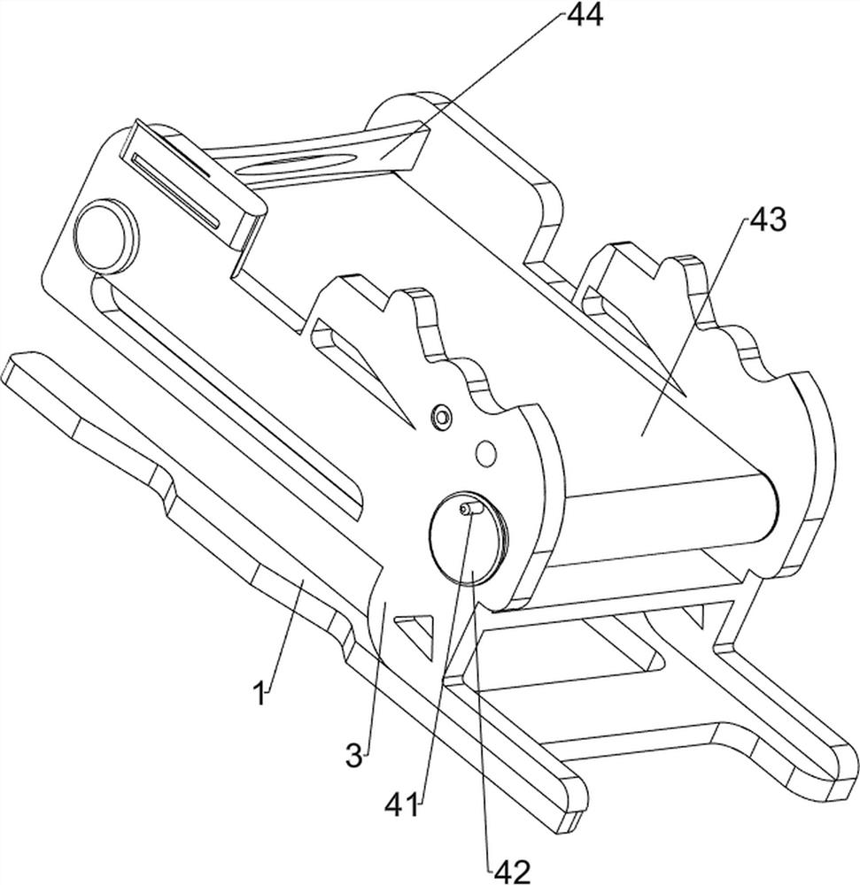
[0067] On the basis of Example 1, such as Figure 2-3 As shown, the rotating mechanism 4 includes a rotating rod 41, a drum 42, a belt 43 and a stopper 44. The front and rear sides of the first fixed mount 3 are symmetrically rotated with a drum 42, and a belt 43 is wound between the two drums 42. The left side of the front roller 42 is provided with a rotating rod 41 , and the rear side of the first fixed frame 3 is provided with a stopper 44 .

[0068] People put the cleaned parts on the belt 43, and then manually rotate the rotating rod 41, so that the front side drum 42 and the belt 43 rotate, thereby driving the rear side drum 42 to rotate, which realizes the transmission function, and the stopper 44 avoids parts Falling out, people collect parts on the front side.

[0069]The spray washing mechanism 5 includes a second fixed frame 51, an extrusion tube 52, an extruded block 53, a groove block 54, a cylinder 55, a feeding tank 56 and a spray cleaning port 57, and the lef...

Embodiment 3

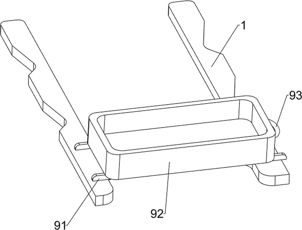
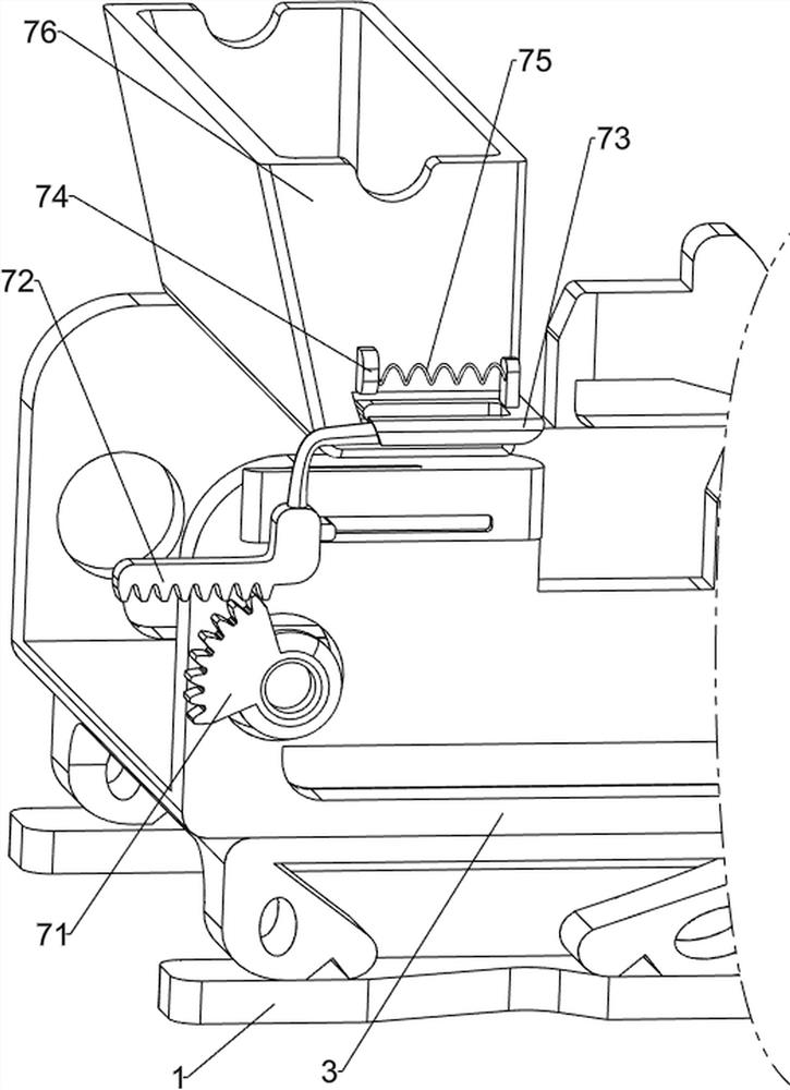
[0072] On the basis of Example 2, such as Figure 4-7 Shown, also include unloading mechanism 7, unloading mechanism 7 comprises missing gear 71, rack 72, baffle plate 73, fixed block 74, spring 75 and feed box 76, first fixed frame 3 top rear sides are provided with material Box 76, material box 76 left side is provided with fixed block 74, and the cylinder 42 left side of rear side is provided with lacking gear 71, and first fixed frame 3 left side rear side sliding type is provided with rack 72, and tooth rack 72 and lacking gear 71 is engaged, the top of the rack 72 is connected with a baffle 73, the baffle 73 is slidably connected with the material box 76, and a spring 75 is connected between the baffle 73 and the fixed block 74.

[0073] People put the parts that need to be cleaned into the material box 76. When the rear side drum 42 rotates, the rear side drum 42 drives the missing gear 71 to rotate, and when the missing gear 71 meshes with the rack 72, it drives the ra...


PUM


Abstract

The invention relates to a cleaning device, in particular to an industrial automatic part cleaning device. The industrial automatic part cleaning device can liberate both hands and improve productivity. The industrial automatic part cleaning device comprises a supporting block, a first fixing frame, a rotating mechanism and a spray-washing mechanism, wherein the supporting block is arranged on the upper portion of a base; the first fixing frame is arranged between the upper portion of the supporting block and the upper portion of the base; the rotating mechanism is arranged at the upper portion of the first fixing frame; and the spray-washing mechanism is arranged on the middle side of the upper portion of the first fixing frame. According to the industrial automatic part cleaning device, a worker places cleaned parts on a belt and then rotates a rotating rod with hand, so that a front roller and the belt rotate, and drive a rear roller to rotate, thereby achieving the conveying effect.

Description

technical field [0001] The invention relates to a cleaning device, in particular to an automatic cleaning device for industrial parts. Background technique [0002] Mechanical parts, also known as mechanical components, are the basic components of machinery. After a period of use, more dirt and impurities will be deposited on the surface of mechanical parts. If they are not cleaned, it will affect the normal use of mechanical parts, and even Affect the normal operation of mechanical equipment, the current common way of parts cleaning is mainly through manual cleaning, the efficiency of manual cleaning is low, and the manual labor intensity is high. [0003] In order to free people's hands and improve productivity, we need to design an automatic cleaning device for industrial parts that can realize automatic cleaning, automatic unloading and automatic collection. Contents of the invention [0004] In order to overcome the shortcomings of low efficiency and high labor inten...

Claims


Application Information

Patent Timeline
IPC IPC(8): B08B3/02B08B1/02B08B1/00B08B13/00B65G15/32B65G23/04
CPCB08B3/022B08B1/02B08B1/002B08B13/00B65G15/32B65G23/04
Inventor 罗丽珍
Owner 罗丽珍
Why Eureka
Try Eureka