
A high-strength and low-elongation printing screen and its production process

A technology for printing screen and production process, applied in printing, printing presses, rotary printing presses, etc., can solve the problems of affecting printing quality, consuming a lot of time, and high cost, reducing labor and replacement time, and reducing disassembly and assembly. The tediousness, simplicity and simplicity of operation

Active Publication Date: 2022-03-15
江阴嘉仕德网业有限公司
View PDF5 Cites 0 Cited by
  • Summary
  • Abstract
  • Description
  • Claims
  • Application Information

AI Technical Summary

Problems solved by technology

[0007] The purpose of the present invention is to provide a high-strength low-extension printing screen and its production process, after solving the short-term work proposed in the above-mentioned background technology, there must be a lot of waste ink on the printing screen, if the waste ink cannot be processed in time Waste ink is easily printed on the printed object, resulting in blurred printed patterns and easily affecting the printing quality; at the same time, the use of high-mesh, fine-diameter polyester screen makes the strength of the mesh itself more and more Low, the elongation of the screen is getting lower and lower, and the dimensional stability of the screen in the printing process is also reduced. The reduction of the area of ​​the metal screen and the use of low-cost edge yarn can indeed greatly reduce the cost of the screen. However, the selection of different side yarns cannot be optimized in the actual application process: polyester mesh is used as the side yarn, which has high elasticity, and the distance between the plate and the pressure required for printing is high, which may easily lead to uneven resilience of the side yarns. , which will eventually lead to deformation of the printed graphics, and printing with a high distance from the plate will easily lead to widening of the printing line; use a metal mesh with a low mesh number and a thick wire diameter as the edge yarn, but the extensibility is too small, and the edge during the printing process Affected by external force, the yarn is prone to irrecoverable deformation and local loss of elasticity; using V-screen material between polyester and wire mesh as edge yarn has high cost and weak strength; after a long time of use, printing screen It will be damaged and needs to be replaced in time, but the existing ones often need to disassemble the entire frame for installing the printing screen, which not only requires a lot of labor, but also consumes a lot of time, which is not conducive to problems related to production efficiency

Method used


Image

  • A high-strength and low-elongation printing screen and its production process
  • A high-strength and low-elongation printing screen and its production process
  • A high-strength and low-elongation printing screen and its production process

Examples


Embodiment 1

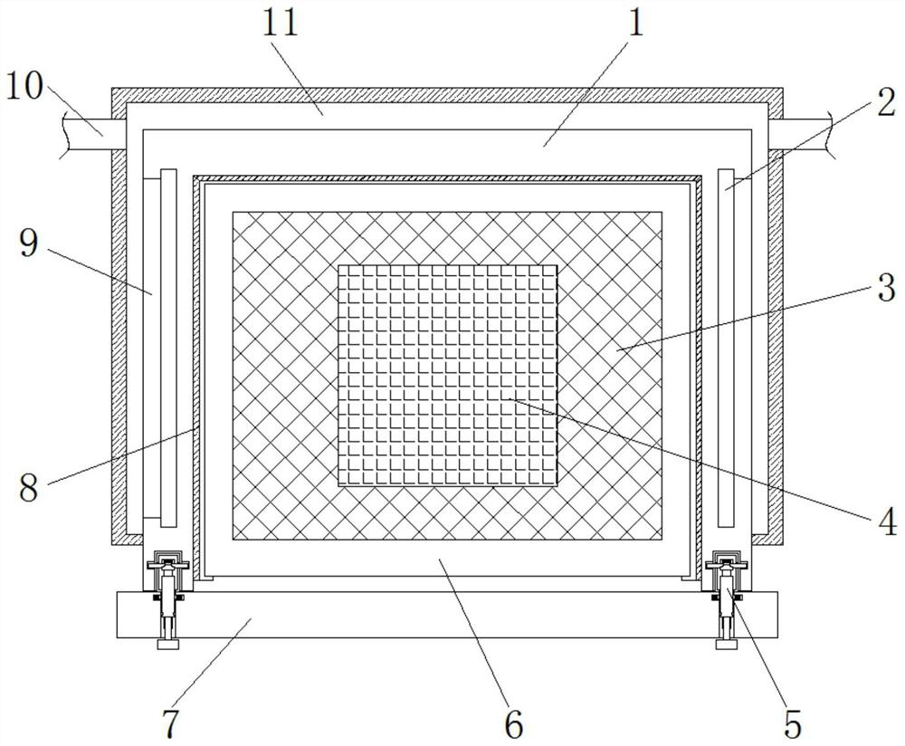
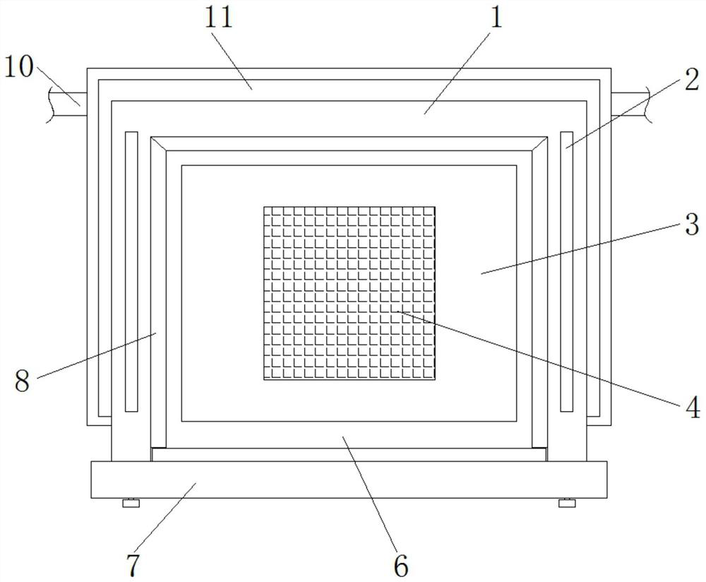
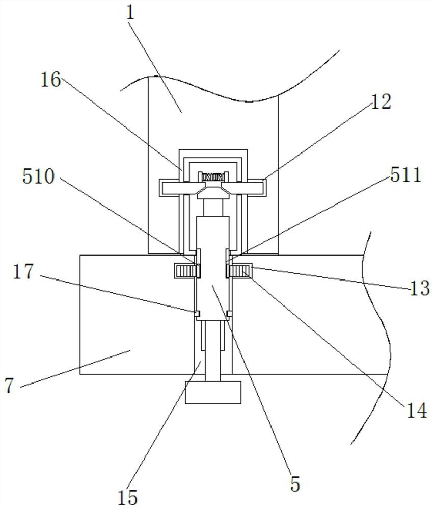
[0036] see Figure 1-7, the present invention provides a technical solution: a high-strength low-stretch printing screen, including a mounting frame 1 and a fixing plate 7, the two sides of the mounting frame 1 and one end of the internal back are provided with mounting slide rails 8, and the mounting frame 1 Both sides of the top are provided with overflow tanks 2, and the sides of the overflow tanks 2 that are far away from each other are provided with connecting grooves 9, and the two sides and one end of the back of the installation frame 1 are provided with ink collecting chambers 11, and the ink collecting chambers 11 are two One end of the back side of the side is provided with a guide tube 10, and the inner sliding sleeve of the three sets of installation slide rails 8 is provided with a printing plate 6, and a printing screen 4 is provided at the middle position inside the printing plate 6, and a printing screen 4 is provided at the edge of the top. There is a metal f...

Embodiment 2

[0038] see Figure 1-7 , the present invention provides a technical solution: a high-strength low-stretch printing screen, including a mounting frame 1 and a fixing plate 7, the two sides of the mounting frame 1 and one end of the internal back are provided with mounting slide rails 8, and the mounting frame 1 Both sides of the top are provided with overflow tanks 2, and the sides of the overflow tanks 2 that are far away from each other are provided with connecting grooves 9, and the two sides and one end of the back of the installation frame 1 are provided with ink collecting chambers 11, and the ink collecting chambers 11 are two One end of the back side of the side is provided with a guide tube 10, and the inner sliding sleeve of the three sets of installation slide rails 8 is provided with a printing plate 6, and a printing screen 4 is provided at the middle position inside the printing plate 6, and a printing screen 4 is provided at the edge of the top. There is a metal ...


PUM


Abstract

The invention discloses a high-strength and low-stretch printing screen and its production process. It includes a mounting frame and a fixing plate. Mounting slide rails are arranged on both sides of the interior of the mounting frame and at one end of the internal back. The top of the mounting frame Both sides are provided with overflow grooves, the sides of the overflow grooves that are far away from each other are provided with connecting grooves, the two sides of the installation frame and one end of the back are provided with ink collection chambers, and the ink collection chambers on both sides One end of the back side is provided with a guide tube, and the inner sliding sleeves of the three sets of the installation slide rails are provided with a printing plate, and a printing screen is provided at the middle position inside the printing plate, and a metal plate is provided at the edge of the top of the printing screen. film, slots are provided on both sides of the front end of the installation frame. The present invention can deal with the waste ink in time when there is a lot of waste ink on the printing screen through the mutual cooperation between the overflow groove, the connecting groove, the guide pipe and the ink collecting chamber, so that the printed pattern is more beautiful and the printing quality is improved. the quality of.

Description

technical field [0001] The invention relates to the technical field of printing screens, in particular to a printing screen with high strength and low elongation and a production process thereof. Background technique [0002] A screen printing machine is a machine that uses a screen printing plate to print, and is a type of printing machine. A screen printing machine is a machine for printing text and images, and is a general term for machines or equipment used to produce printed matter. The screen printing machine is a representative printing equipment in the stencil printing machine. In addition to silk, the material for making the screen can also be nylon wire, copper wire, steel wire or stainless steel wire. The squeegee squeezes the ink, and then the ink is printed on the substrate by the screen printing plate through the squeegee. [0003] There are certain deficiencies in the current printing screen board: [0004] 1. After the period of work, there will inevitably...

Claims


Application Information

Patent Timeline
Patent Type & Authority Patents(China)
IPC IPC(8): B41F15/34B41F15/36B41C1/14B41F31/20
CPCB41F15/34B41F15/36B41C1/14B41F31/20
Inventor 周夏
Owner 江阴嘉仕德网业有限公司
Learn More