A chain drive conveying device

A technology of chain drive and mounting frame, which is applied in the direction of transportation, packaging, and conveyors. It can solve the problems of unsteady clamping of cylindrical materials, complex structure, and large footprint, and achieve convenient and fast positioning, clamping, and conveying efficiency. High, good bearing capacity

Active Publication Date: 2022-03-08
JILIN UNIV
View PDF0 Cites 0 Cited by
  • Summary
  • Abstract
  • Description
  • Claims
  • Application Information

AI Technical Summary

Problems solved by technology

The feeding machine generally transports materials to different heights, has a complex structure and occupies a large area. Now, more and more materials are transported by chain drive conveyors.
[0003] At present, the chain drive conveying device that appears on the market cannot quickly and firmly clamp the cylindrical material when conveying the cylindrical material

Method used


Image

  • A chain drive conveying device
  • A chain drive conveying device
  • A chain drive conveying device

Examples


Embodiment Construction

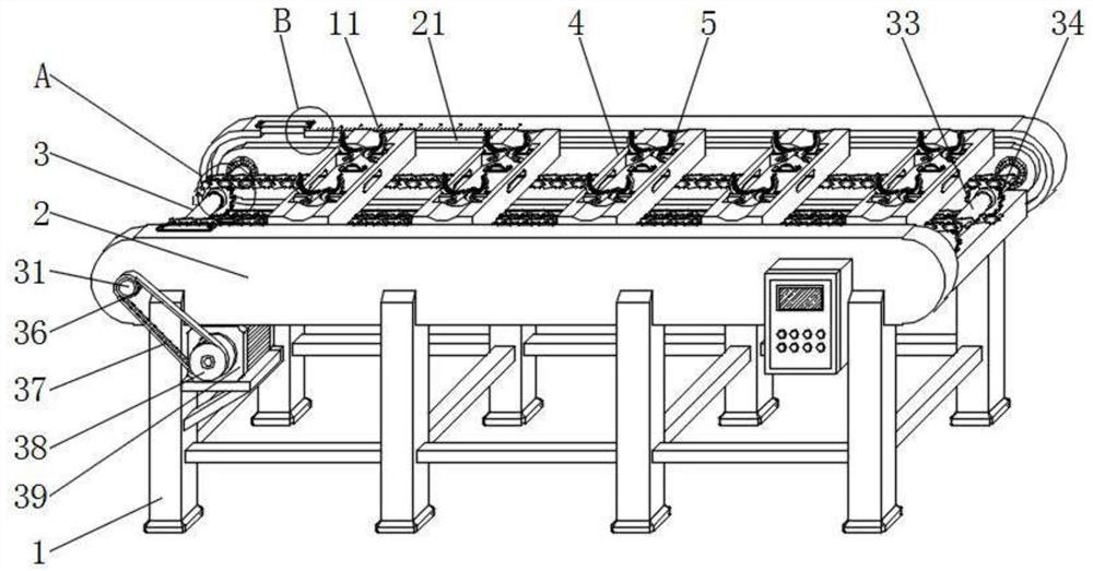
[0019] see Figure 1 to Figure 5 As shown, a chain drive conveying device: including a base 1, a mounting frame 2, a driving mechanism 3, several connecting mechanisms 4 and several clamping mechanisms 5, the upper end of the base 1 is provided with a mounting frame 2, and the driving mechanism 3 is provided with In the middle of the mounting frame 2, several connecting mechanisms 4 are evenly arranged on the inside of the mounting frame 2 through the driving mechanism 3, and the connecting mechanisms 4 can move in the mounting frame 2 driven by the driving mechanism 3, and the clamping mechanism 5 is symmetrically arranged on the mounting frame 2. On the connecting mechanism 4;

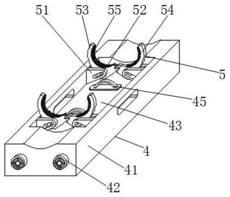
[0020] The clamping mechanism 5 includes a mounting seat 51, an arc-shaped left half claw 53, an arc-shaped right half claw 54 and a rubber pad 55. The mounting seat 51 is fixedly welded on the inner side of the connecting mechanism 4, and the middle part of the mounting seat 51 is provided with a co...


PUM


Abstract

The invention discloses a chain drive conveying device, which comprises a base, a mounting frame, a driving mechanism, several connecting mechanisms and several clamping mechanisms, the upper end of the base is provided with a mounting frame, and the driving mechanism is arranged The two connecting mechanisms are evenly arranged on the inside of the mounting frame through the driving mechanism, and the connecting mechanism can move in the mounting frame driven by the driving mechanism, and the clamping mechanism is symmetrically arranged on the connecting mechanism; in the device of the present invention, a special clamp is provided. The holding mechanism uses the self-weight of the material to realize the clamping of the material. It is easy to operate and convenient for quick positioning and clamping and quick unloading during use, and it is relatively firm after clamping to avoid shaking or falling off of the material during the conveying process, and The clamping mechanism adopts a detachable connection mechanism, which facilitates the increase and decrease of the number of clamping parts and the adjustment of their spacing. At the same time, the drive of the chain is used as the power as a whole, which has greater strength and better carrying capacity.

Description

technical field [0001] The invention relates to the field of conveying devices, in particular to a chain-driven conveying device. Background technique [0002] Conveying devices are often used in logistics or conveying industrial equipment. Common conveyors include belt conveyors, screw conveyors, feeders, etc. Belt conveyors are generally driven by friction and cannot transmit high power. There is slippage in the transmission, which is generally not suitable for occasions with heavy materials; moreover, the belt wears quickly and has a short service life. The screw conveyor realizes the conveying through the auger, and the equipment occupies a large space. The feeder generally transports materials to different heights, has a complex structure and occupies a large area. Now, more and more materials are transported by chain drive conveyors. [0003] At present, the chain drive conveying devices appearing on the market cannot quickly and stably clamp the cylindrical materia...

Claims


Application Information

Patent Timeline
Patent Type & Authority Patents(China)
IPC IPC(8): B65G17/32
CPCB65G17/326B65G2201/0217
Inventor 程亚兵高俊珂李家宝刘雨朱凯宏许宛仟王天娇
Owner JILIN UNIV
Why Eureka
Try Eureka