Multifunctional loading and unloading integrated robot

A robot and multi-functional technology, applied in the direction of conveyors, conveyor objects, transportation and packaging, etc., can solve the problems of low loading and unloading efficiency, single function, inconvenient adjustment and use, etc., to achieve the effect of improving functionality and convenient adjustment

Inactive Publication Date: 2021-08-31
合肥哈工库讯智能科技有限公司
View PDF0 Cites 5 Cited by
  • Summary
  • Abstract
  • Description
  • Claims
  • Application Information

AI Technical Summary

Problems solved by technology

[0004] A multifunctional loading and unloading integrated robot proposed by the present invention solves the problems that the existing loading and unloading integrated robot is inconvenient for flexible adjustment and use, has a single function, and has low loading and unloading efficiency

Method used


Image

  • Multifunctional loading and unloading integrated robot
  • Multifunctional loading and unloading integrated robot
  • Multifunctional loading and unloading integrated robot

Examples


Embodiment 1

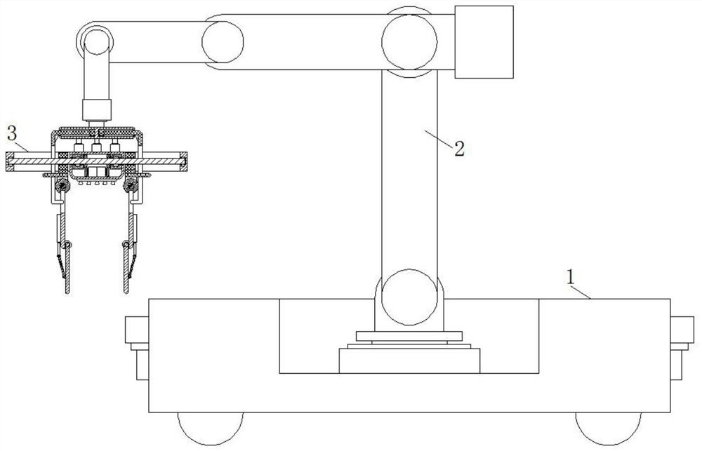
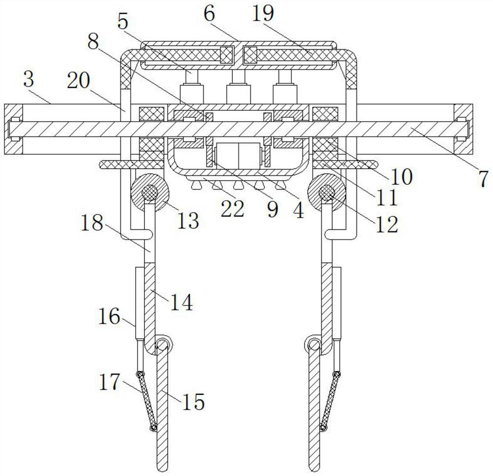
[0028] refer to Figure 1-3 As shown, a multifunctional loading and unloading integrated robot includes an omnidirectional vehicle platform 1, a six-axis mechanical arm 2, and a square frame 3. An equipment compartment 4 is fixedly connected between the front and rear inner walls of the square frame 3. The upper part of the equipment compartment 4 A push rod motor 5 is fixedly mounted on the end face array, and the upper end of the push rod motor 5 is fixedly connected to the limit cylinder 6, and the lower end face of the equipment compartment 4 is fixedly mounted with a suction cup 22, which is characterized in that the front and rear sides of the square frame 3 A screw rod 7 is rotatably connected between the left and right inner walls, and the screw rod 7 passes through the equipment box 4 and is fixedly fitted with a first gear 8 on the surface of the equipment compartment 4. The lower inner wall of the equipment compartment 4 is fixedly equipped with a first motor and a s...

Embodiment 2

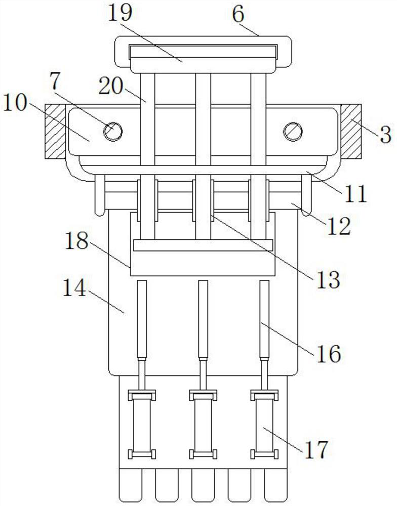
[0030] refer to Figure 1-3 As shown, under the condition that the other parts are the same as those in Embodiment 1, the difference between this embodiment and Embodiment 1 is that the two ends of the limit slide rods 19 on both sides that are close to each other are respectively slid to be arranged on the two ends of the limit cylinder 6. The sides of the third gears 13 on both sides that are far away from each other extend on the side where the sliders 10 on both sides are far away from each other, and the lower end of each rack 20 extends below the mounting plate 11 through the slideway opening 21, The racks 20 on both sides are respectively arranged on the side where the third gears 13 on both sides are away from each other and meshed with the third gear 13. The lower end of each rack 20 is movably arranged in the opening 18 on the respective side, and then The push rod motor can drive the limit cylinder 6 to move up relative to the square frame, so that the limit slide rod...


PUM


Abstract

The invention discloses a multifunctional loading and unloading integrated robot, relates to the field of loading and unloading integrated robots, and provides the following scheme for solving the problems that an existing loading and unloading integrated robot is inconvenient to adjust and use flexibly, single in function and low in loading and unloading efficiency: the multifunctional loading and unloading integrated robot comprises an omni-directional vehicle platform, a six-axis mechanical arm and a square frame. An equipment bin is fixedly connected to the inner wall of the square frame, a push rod motor and a limiting barrel are fixedly installed on the upper end face of the equipment bin in an array mode, a suction cup is fixedly installed on the lower end face of the equipment bin, a screw is rotationally connected into the square frame, the surface, in the equipment bin, of the screw is fixedly sleeved with a first gear, and the two ends of the screw are both sleeved with sliding blocks in a threaded mode. A clamping mechanism is arranged on the lower end face of the sliding block, and an adjusting mechanism is arranged in the limiting cylinder. The multifunctional loading and unloading integrated robot has the characteristics that the robot can be conveniently adjusted, objects with different sizes, shapes and weights can be conveniently fastened and clamped, and the functionality of the robot is greatly improved.

Description

technical field [0001] The invention relates to the field of integrated loading and unloading robots, in particular to a multifunctional integrated loading and unloading robot. Background technique [0002] The automatic loading and unloading robot can be used to replace the manual handling of material packages for loading operations. It is not only suitable for working environments with a lot of dust and other poor environments, it reduces the potential safety hazards that may exist in manual handling, and has high work efficiency. However, since the length and width of the material packages are usually not equal, and the dimensions of the carriages are not exactly the same, in order to make full and reasonable use of the space in the carriages, it is necessary to unify the orientation of the material packages during loading. During manual operation, although it is possible to identify and adjust the orientation of the unified material package, the labor cost is high, the l...

Claims


Application Information

Patent Timeline
Patent Type & Authority Applications(China)
IPC IPC(8): B65G47/90B65G47/91
CPCB65G47/902B65G47/914B65G2201/02
Inventor 张魏魏周洋洋屈海峰
Owner 合肥哈工库讯智能科技有限公司
Why Eureka
Try Eureka