Device capable of replacing and recovering steel wire rope anchor rod and recovering method

A technology of steel wire rope and wire rope sleeve, which is applied in construction, sheet pile wall, infrastructure engineering and other directions, can solve the problems of cumbersome operation process, low recovery value and high production cost, and achieves efficient operation, easy preservation and management, and low cost. Effect

Pending Publication Date: 2021-08-31
GUANGXI UNIV
View PDF21 Cites 0 Cited by
  • Summary
  • Abstract
  • Description
  • Claims
  • Application Information

AI Technical Summary

Problems solved by technology

However, most of these bolt recycling forms have disadvantages such as complex structure, cumbersome operation process, expensive materials, and high production cost. It is often inconvenient to carry out construction under specific circumstances, and the recycling value is not high.

Method used


Image

  • Device capable of replacing and recovering steel wire rope anchor rod and recovering method
  • Device capable of replacing and recovering steel wire rope anchor rod and recovering method

Examples


Embodiment 1

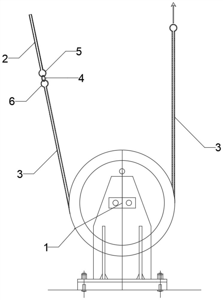
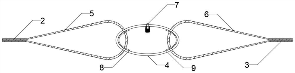
[0026] Such as Figure 1 to Figure 2 As shown, the device of the present invention that can replace and reclaim the wire rope anchor, the components include a static pulley 1, a new wire rope anchor 2, an old wire rope anchor 3, a wire rope collar 4, a bolt 7, a left gasket 8 and The right gasket 9, the specific structure and connection relationship of the components are:

[0027] The static pulley 1 is fixed on the rock mass, and the new wire rope anchor 2 and the old wire rope anchor 3 are supported by the static pulley 1 to play the role of pulling support. The heart ring 5 of the new wire rope anchor 2 is connected with the heart ring 6 of the old wire rope anchor 3 through the wire rope collar 4, so as to realize the connection between the new and old wire rope anchors. Same as the wire rope anchors on the market, the heart ring is a structure embedded in the bend of the wire rope and fixed with a rope clip or an aluminum alloy fastening sleeve. Wire rope collar 4 insid...

Embodiment 2

[0031] A recovery method suitable for a device capable of replacing and recovering a wire rope anchor, comprising the steps of:

[0032] (1) When the old steel wire rope 3 needs to be replaced due to reasons such as corrosion and metal fatigue, first remove the bolt 7 of the steel wire rope collar 4, and remove the heart ring 6 on one side of the old steel wire rope anchor rod 3 from the supporting structure, and put the It and the heart ring 5 on one side of the new wire rope anchor rod 2 are respectively placed on the left gasket 8 and the right gasket 9 of the wire rope collar 4, and then the bolt 7 of the wire rope collar 4 is tightened;

[0033] (2) Put the heart ring 5 and the heart ring 6 at both ends of the new wire rope anchor 2 and the old wire rope anchor 3 into the two ends of the wire rope collar 4 respectively, so that the new steel rope anchor 2 and the old wire rope The anchor rods 3 are connected to each other; in this process, the other end of the old wire ro...


PUM


Abstract

The invention relates to the technical field of anchor rods, in particular to a device capable of replacing and recovering a steel wire rope anchor rod. The device comprises a static pulley, a steel wire rope lantern ring, a new steel wire rope anchor rod and an old steel wire rope anchor rod, wherein the static pulley is fixed to a rock mass, the old steel wire rope anchor rod is wound round the static pulley to be connected to the new steel wire rope anchor rod, and the new steel wire rope anchor rod is connected with the old steel wire rope anchor rod through the steel wire rope lantern ring. When the new steel wire rope anchor rod and the old steel wire rope anchor rod are replaced by means of the steel wire rope lantern rings, the new steel wire rope anchor rod and the old steel wire rope anchor rod are mutually connected, and the anchor rods are replaced by pulling the steel wire rope anchor rods. The device is simple in structure, anchor rods can be effectively recovered, and the purposes of reducing construction cost, saving natural resources, achieving safe construction, guaranteeing the environment and the like are achieved.

Description

technical field [0001] The invention relates to the technical field of anchor rods, in particular to a device and a recovery method for replacing and recovering steel wire rope anchor rods. Background technique [0002] With the continuous advancement and improvement of infrastructure construction, various civil engineering projects have been launched rapidly, and bolt support technology is widely used to reinforce various foundation pits. Traditional bolts are difficult to recycle during construction, and there are still residues after withdrawal, which makes the underground construction space occupied, which not only adversely affects construction safety but also damages the underground environment. [0003] Today, with the increasingly mature bolt support technology, there are many types of recyclable bolts on the market, including mechanical combination recovery type, hot melt recovery type and other forms. However, most of these bolt recycling forms have disadvantages ...

Claims


Application Information

Patent Timeline
Patent Type & Authority Applications(China)
IPC IPC(8): E02D5/74E02D11/00E02D13/00
CPCE02D5/74E02D11/00E02D13/00E02D2600/30
Inventor 马少坤周易周颖叶炀城张文俊韩宇马伟智
Owner GUANGXI UNIV
Why Eureka
Try Eureka