Floor drain device capable of automatically and circularly removing dirt

An automatic circulation and floor drain technology, which is applied to water supply devices, waterway systems, drainage structures, etc., can solve the problems of limited installation space of floor drain devices, difficulty in installation and construction, and loss of parts, etc., to achieve simple structure, ensure installation efficiency, The effect of preventing clogging

Pending Publication Date: 2021-08-31
ZHEJIANG YASHA DECORATION
View PDF1 Cites 0 Cited by
  • Summary
  • Abstract
  • Description
  • Claims
  • Application Information

AI Technical Summary

Problems solved by technology

However, the floor drain device described in this invention has a relatively complicated structure, and the floor drain mechanism and the filter plate need to be taken out when cleaning the filtered sundries, which is difficult to clean and easily causes parts to be lost, which can easily affect subsequent use; in addition, due to When decorating the home environment, the installation space of the floor drain device is limited, and the floor drain device with a complex structure and a large volume will cause problems such as difficult installation and construction.

Method used


Image

  • Floor drain device capable of automatically and circularly removing dirt
  • Floor drain device capable of automatically and circularly removing dirt
  • Floor drain device capable of automatically and circularly removing dirt

Examples


Embodiment 1

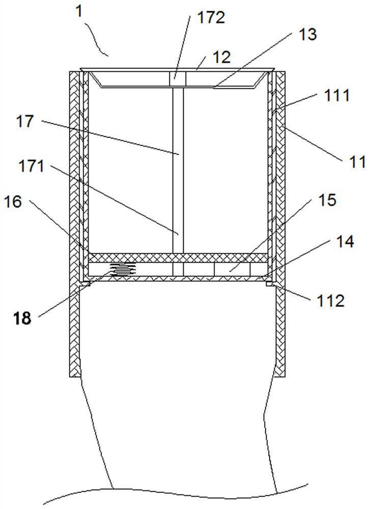
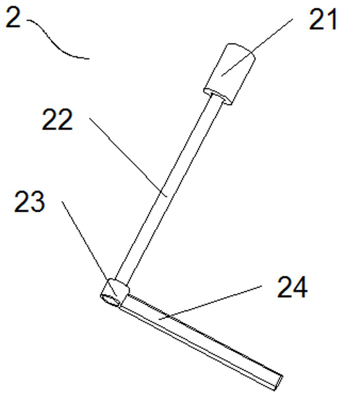
[0033] A floor drain device diagram for automatic cycle decontamination, including a debris collection mechanism 1 and a debris cleaning mechanism 2; 1 is a schematic diagram of the debris collection mechanism, figure 2 Schematic diagram for debris cleaning mechanism, such as figure 1 and figure 2As shown, the debris collection mechanism 1 includes a casing 11 arranged in the drainage pipe, a floor drain cover 12 arranged at the water inlet of the casing 11, a floor drain cover 12 arranged at the bottom of the floor drain cover 12 and connected to the The filter screen 13 connected to the floor drain cover 12, the filter cartridge 14 arranged in the casing 11, the gravity sensor 15 arranged at the bottom of the filter cartridge 14, and the filter plate 16 arranged above the gravity sensor 15 And one end is rotationally connected with the bottom of the filter cartridge 14, and the other end is connected with the central rotating shaft 17 of the floor drain cover 12; the debr...


PUM


Abstract

The invention discloses a floor drain device capable of automatically and circularly removing dirt. The floor drain device capable of automatically and circularly removing the dirt comprises a sundry collecting mechanism (1) and a sundry cleaning mechanism (2), wherein the sundry collecting mechanism comprises a sleeve (11), a floor drain cover (12) arranged at a water inlet of the sleeve, a filtering screen (13) arranged on the lower part of the floor drain cover, a filtering cylinder (14) arranged in the sleeve, a gravity sensor (15) arranged at the bottom of the filtering cylinder, a filtering plate (16) arranged above the gravity sensor and a central rotating shaft with one end rotationally connected with the bottom of the filtering cylinder and the other end connected with the floor drain cover, wherein the sundry cleaning mechanism comprises a driving motor (21), a driving shaft (22) connected with the driving motor, a spline housing (23) arranged at the end of the driving shaft and a cleaning rotating arm (24) arranged on the outer side surface of the spline housing; the central rotating shaft penetrates through the filtering plate and the filtering screen. According to the floor drain device capable of automatically and circularly removing the dirt, the situation that a drainage pipeline is blocked can be prevented, filtered sundries can be conveniently cleaned, and the floor drain device is simple in structure and convenient to install.

Description

technical field [0001] The invention relates to the technical field of drainage devices, in particular to a floor drain device for automatic cycle decontamination. Background technique [0002] The floor drain is an important interface connecting the drainage system with the indoor ground. As an important part of the drainage system in the residence, the floor drain needs to filter out impurities in the sewage under the premise of ensuring the water speed to prevent the blockage of the drainage system. The floor drains in the prior art generally only include a simple first-stage filter device, which can simply filter the impurities contained in the sewage, but cannot filter the relatively fine debris, and often the drainage pipes are blocked due to insufficient filtration. If it is unblocked, it is necessary to ask professional maintenance personnel to unclog it, which wastes manpower and money at the same time. The floor drain device with multi-stage filtration can filter ...

Claims


Application Information

Patent Timeline
IPC IPC(8): E03F5/04E03F7/00
CPCE03F5/0407E03F7/00
Inventor 丁欣欣丁泽成周东珊陈文静余广
Owner ZHEJIANG YASHA DECORATION
Why Eureka
Try Eureka