Differential pressure sliding sleeve and oil-gas well fracturing construction method

A technology of differential pressure sliding sleeve and construction method, which is applied in earthwork drilling, wellbore/well components, wellbore/well valve devices, etc., which can solve the difficulty of opening ordinary differential pressure sliding sleeves and construction operations of differential pressure sliding sleeves Problems such as small window and small range of pressure work

Pending Publication Date: 2021-08-31
CHINA PETROLEUM & CHEM CORP +1
View PDF6 Cites 1 Cited by
  • Summary
  • Abstract
  • Description
  • Claims
  • Application Information

AI Technical Summary

Problems solved by technology

However, there are still some problems with the existing differential pressure sleeve
For example, the success rate of opening is low, and the window left for the construction operation of the differential pressure sliding sleeve is small
At present, the pressure test of the entire wellbore of shale gas wells is above 90MPa, and the pressure level of the wellhead device is 105MPa, which makes the pressure range of the allowable opening differential pressure sliding sleeve small, making it difficult for ordinary differential pressure sliding

Method used


Image

  • Differential pressure sliding sleeve and oil-gas well fracturing construction method
  • Differential pressure sliding sleeve and oil-gas well fracturing construction method

Examples


Embodiment Construction

[0023] The present invention is introduced below by accompanying drawing.

[0024] In this application, it should be noted that the end of the differential pressure sliding sleeve according to the present invention that is run into the wellbore near the wellhead is defined as the upper end, and the end away from the wellhead is defined as the lower end.

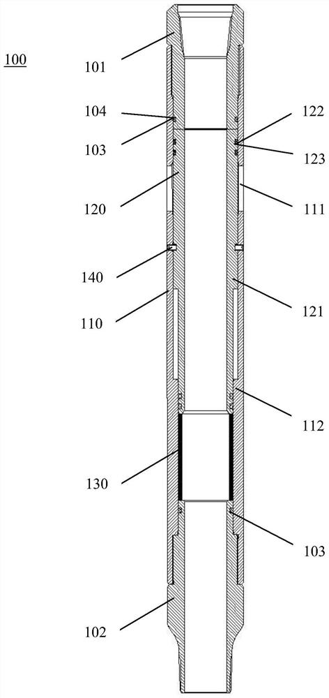
[0025] figure 1 The construction of the differential pressure sleeve 100 according to the invention in the closed state is shown. Such as figure 1 As shown, the differential pressure sliding sleeve 100 includes an outer cylinder 110 . In one embodiment, both ends of the outer cylinder 110 are configured as negative step-shaped connecting buckles. Two ends of the outer cylinder 110 are respectively connected with an upper joint 101 and a lower joint 102 for connecting a downhole string. In one embodiment, the two ends of the outer cylinder 110 are respectively configured as positive step-shaped connecting buckles, and the ...


PUM


Abstract

The invention provides a differential pressure sliding sleeve. The differential pressure sliding sleeve comprises an outer cylinder, an upper connector, a lower connector, an inner cylinder and a bearing ring, wherein a plurality of flow guide holes are formed in the side wall of the outer cylinder; the upper connector and the lower connector are arranged at the two ends of the outer cylinder and used for being connected with an underground pipe column respectively; the inner cylinder is arranged in the outer cylinder and used for sealing the flow guide holes; the bearing ring is arranged between the lower connector and the inner cylinder and can be dissolved under the action of working fluid; and the area of the upper end face of the inner cylinder is set to be larger than that of the lower end face of the inner cylinder so that the working fluid can form a pressure difference between the axial end faces of the inner cylinder to provide downward pressure for the inner cylinder, and then the inner cylinder can move downwards under the action of the pressure after the bearing ring is dissolved to open the flow guide holes. The invention further provides an oil-gas well fracturing construction method using the differential pressure sliding sleeve.

Description

technical field [0001] The invention relates to the technical field of oil and gas well completion and reservoir transformation, in particular to a differential pressure sliding sleeve. The invention also relates to an oil and gas well fracturing construction method. Background technique [0002] In recent years, oil and gas well exploration and development projects have developed rapidly. At present, in the vigorous development of shale gas wells, there are generally two ways to fracturing the first stage of shale gas wells, one is to use coiled tubing perforation, and the other is to use differential pressure sliding sleeves. The coiled tubing perforation method is mainly used to open the first section of the wellbore, and it is a relatively mature technical method in the application of opening the first section of the wellbore at present. However, when the coiled tubing perforation method is applied in shale gas wells, the construction time is low and the construction c...

Claims


Application Information

Patent Timeline
IPC IPC(8): E21B34/08E21B43/26
CPCE21B34/08E21B43/26
Inventor 林永茂赵伟胡丹崔警宇陈晨周怡君刘涛滕汶江钱江李腾飞
Owner CHINA PETROLEUM & CHEM CORP
Why Eureka
Try Eureka