Cremator cleaning terminal for environmental protection
A cremation furnace and environmental protection technology, which is applied in the directions of incinerators, furnace grate, methods of incinerating corpses, etc., can solve the problems of easy burns, not meeting the needs of use, large incineration dust, etc., to save energy and prevent dust from adhering to the inner wall surface. , the effect of improving the effect
- Summary
- Abstract
- Description
- Claims
- Application Information
AI Technical Summary
Problems solved by technology
Method used
Image
Examples
Embodiment 1
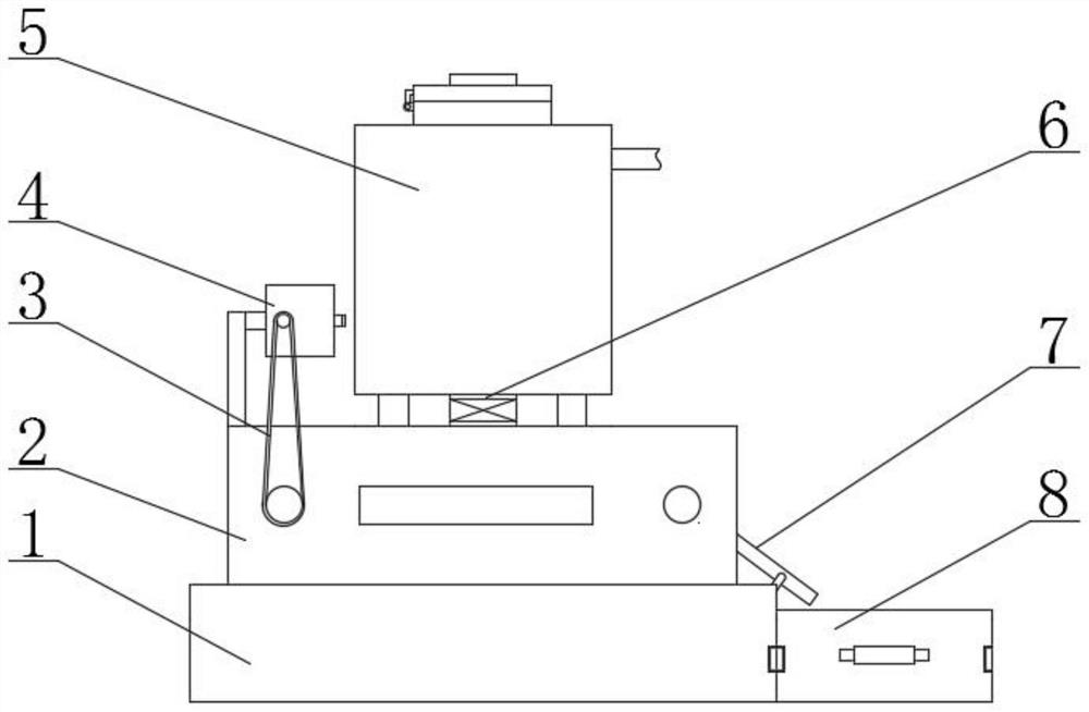
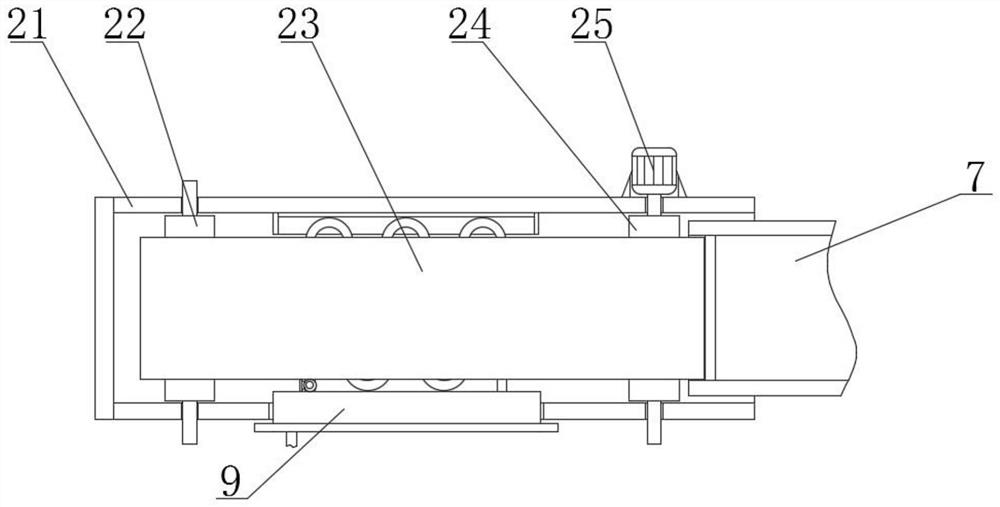
[0027] see Figure 1-5, the present invention provides a technical solution: an environmentally friendly cremation furnace cleaning terminal, a base 1; a conveying mechanism 2, the conveying mechanism 2 includes a fixed frame 21, a driven shaft 22, a conveyor belt 23, a driving shaft 24 and a motor 25. A fixed frame 21 is fixedly installed on the top of the base 1, and a driven shaft 22 is rotatably connected between the inner walls of the fixed frame 21, and both ends of the driven shaft 22 pass through the side wall of the fixed frame 21 and Extending to the outside of the fixed frame 21, the inner wall of the fixed frame 21 and one end away from the driven shaft 22 is rotatably connected with a drive shaft 24, and both ends of the drive shaft 24 pass through the side wall of the fixed frame 21 and extend to the fixed frame 21. Outside the frame 21, the drive shaft 24 extends to one end of the fixed frame 21 and a motor 25 is fixedly installed, and a conveyor belt 23 is arra...
Embodiment 2
[0029] As a preferred solution of Embodiment 1, first magnets are fixedly installed at both ends of the collection box 8, and second magnets compatible with the first magnets are fixedly installed on the side wall of the base 1, which can The collection box 8 is limited to avoid the problem that the collection box 8 is separated from the base 1 due to vibration, thereby causing dust to fall to the ground.
Embodiment 3
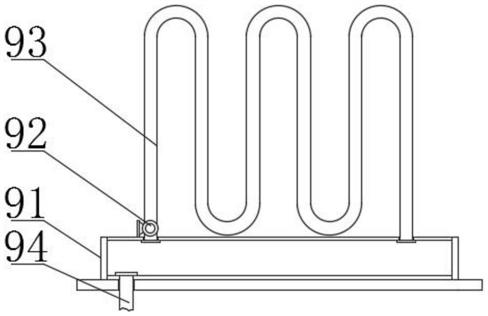
[0031] As a preferred solution of Embodiment 1, a cooling mechanism 9 is fixedly installed on the side wall of the fixed frame 21 and between the conveyor belts 23, and the cooling mechanism 9 includes a liquid storage box 91, a water pump 92, and a heat exchange tube 93 and the liquid inlet pipe 94, the side wall of the fixed frame 21 is movably inserted between the conveyor belts 23 with a liquid storage box 91, and one end of the liquid storage box 91 located inside the fixed frame 21 is fixedly installed with a heat exchange tube 93 A water pump 92 is fixedly installed inside one end of the heat exchange tube 93, and the water pump 92 is fixedly installed with the liquid storage box 91 through a bracket. 94, the water pump 92 is electrically connected to the control module 10, the heat exchange tube 93 adopts a serpentine structure, and the inner wall of the fixed frame 21 and the side away from the liquid storage box 91 are fixedly installed with a placement frame, and Th...
PUM
 Abstract
Description
Claims
Application Information
 - R&D
- Intellectual Property
- Life Sciences
- Materials
- Tech Scout
- Unparalleled Data Quality
- Higher Quality Content
- 60% Fewer Hallucinations
Browse by: Latest US Patents, China's latest patents, Technical Efficacy Thesaurus, Application Domain, Technology Topic, Popular Technical Reports.
© 2025 PatSnap. All rights reserved.Legal|Privacy policy|Modern Slavery Act Transparency Statement|Sitemap|About US| Contact US: help@patsnap.com


