Frequency multiplication method for Hall speed sensor at shaft end

A speed sensor and Hall device technology, which is applied in the field of frequency multiplication of Hall speed sensors at the shaft end, can solve the problems of limited sensor installation space and signal frequency that cannot meet the use requirements, so as to improve the service life and realize the effect of signal induction

Pending Publication Date: 2021-08-31
HUNAN XIANGYI RAILROAD LOCOMOTIVE ELECTRICAL EQUIP
View PDF2 Cites 2 Cited by
  • Summary
  • Abstract
  • Description
  • Claims
  • Application Information

AI Technical Summary

Problems solved by technology

[0004] The present invention aims at the speed sensor of the traction system of some subways with severe working conditions. When the Hall speed sensor needs to be used to replace the currently used photoelectric speed sensor, due to the limited installation space of the sensor, the output signal frequency is guaranteed under the condition of the gear tooth spacing. To solve the problem of not being able to meet the requirements of use, a method of multiplying the frequency of the Hall speed sensor at the shaft end is proposed, so that the output frequency can not only meet the requirements of use, but also not increase the processing difficulty of the gear, and can also ensure the quality of the sensor

Method used


Image

  • Frequency multiplication method for Hall speed sensor at shaft end
  • Frequency multiplication method for Hall speed sensor at shaft end
  • Frequency multiplication method for Hall speed sensor at shaft end

Examples


Embodiment 1

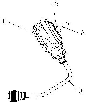
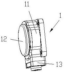
[0033] A frequency doubling method for a shaft-end Hall speed sensor, such as figure 1 As shown, the shaft-end Hall speed sensor includes a housing 1 and a transmission shaft 21, such as figure 2 As shown, the housing 1 includes a mounting base 11, an outer cover 12 and a connecting head 13. The transmission shaft 21 is connected to the mounting base 11 through a bearing 23 as a whole, one end of which is located in the housing 1, and the gear 4 is installed on the transmission shaft 21 in the housing. One end inside the gear 1 rotates synchronously with the drive shaft 21 , and the hall element 511 for receiving induction is arranged on the outer circumference of the gear 4 and is located in the connector 13 , and the induction signal is output through the cable 3 .

[0034] Due to the limited installation space, the size of the gear 4 is limited, and in order to meet the requirements of the speed sensor, the number of pulses output by each revolution of the gear should not ...

Embodiment 2

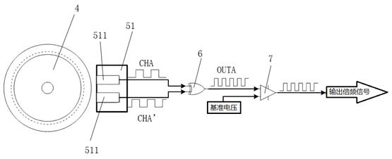
[0038] This embodiment is the specific use of the above-mentioned embodiment. In this embodiment, the gear 4 modulus used is 1, that is, the pitch between the teeth is π mm, and the distance between the sensing points of the two Hall elements 511 in the Hall device 51 is Therefore, the position of the Hall device 5 on the outer periphery of the gear 4 is: the angle between the line connecting the sensing points of the Hall element 511 and the rotation direction of the gear 4 is acos((π / 4) / 1.75), which is about 63.346°, at this time, the projected distance of the line between the sensing points on the rotation direction of gear 4 is (π / 4) mm, so that the phase difference between CHA and CHA', and the phase difference between CHB and CHB' are both 90 °. According to the size of the housing 1 and the size of the Hall device 51, the natural number n is selected to be 5, that is, the midpoint line between the respective sensing point lines L1 and L2 in the two Hall devices 51 is ro...

Embodiment 3

[0041] This embodiment is an improvement made on the basis of the above-mentioned embodiments, such as Figure 7 As shown, in order to meet the requirement that the transmission shaft 21 not only transmits the rotational speed but also provides support, a flange 22 is provided at the end where the transmission shaft 21 is connected to the shaft end to form a flange transmission shaft 2, as shown in Figure 8 As shown, the flange transmission shaft 1 is an integral structure of the flange 22 and the transmission shaft 21. Through the connection between the flange 22 and the shaft end, the force bearing area of ​​the transmission shaft 2 is greatly increased and its service life is prolonged.

[0042] like Figure 9 As shown, the gear 4 is arranged at the end of the flange transmission shaft 2 away from the flange 22, and a bearing 23 is provided on the outside of the transmission shaft 21 between the gear 4 and the flange 22 to support the housing 1, so that the gear 4 Relativ...


PUM


Abstract

The invention relates to a frequency multiplication method for a Hall speed sensor at a shaft end. According to the method, two square wave signals having the same frequency and output by two Hall elements pass through an exclusive-OR gate to obtain a frequency-multiplied square wave signal; and since the two Hall elements are arranged on the outer periphery of a gear and the projection distance of a connecting line between induction points of the two Hall elements in the rotation direction of the gear is m pi / 4, a phase difference between the two square wave signals with the same frequency is 90 degrees, and the duty ratio of square wave signals obtained after frequency multiplication is 50%, wherein m is the modulus of the gear. According to the invention, the positions of the two Hall elements on the outer periphery of the gear are reasonably arranged, so the phase difference between the two paths of square wave signals with the same frequency before frequency multiplication is 90 degrees, the duty ratio of the square wave signal after frequency multiplication is ensured to be 50%, and high-level time and low-level time in output signals reach the maximum and are thus better identified.

Description

technical field [0001] The invention relates to a frequency multiplication method of a sensor, in particular to a frequency multiplication method of a shaft end Hall speed sensor. Background technique [0002] At present, the speed sensors of the traction system of some subways use photoelectric speed sensors. According to the failure statistics of the depot, the failure rate of the photoelectric speed sensors that have been in operation for about 3 years is as high as 40% to 50%. Parts with weak resistance to vibration and impact, such as relays. However, the Hall speed sensor used in the brake system and the eddy current speed sensor used in the signal system with strong shock resistance in other axle positions of the same car have a lower failure rate. Due to the particularity of this part of the subway line and the vehicle traction mode, the sensor is directly connected to the end of the axle. During the running of the train, the drive shaft not only provides the rotati...

Claims


Application Information

Patent Timeline
Patent Type & Authority Applications(China)
IPC IPC(8): G01P3/42
CPCG01P3/42
Inventor 杨明义曾育博杨雨恋郑骤
Owner HUNAN XIANGYI RAILROAD LOCOMOTIVE ELECTRICAL EQUIP
Why Eureka
Try Eureka